LIGHTING SYSTEM Footwell Light Circuit
DESCRIPTION
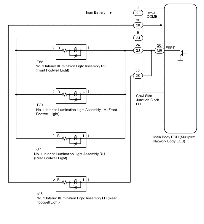
The main body ECU (multiplex network body ECU) controls the operation of the following lights:
-
No. 1 Interior Illumination Light Assembly LH (Front Footwell Light)
-
No. 1 Interior Illumination Light Assembly RH (Front Footwell Light)
-
No. 1 Interior Illumination Light Assembly LH (Rear Footwell Light)
-
No. 1 Interior Illumination Light Assembly RH (Rear Footwell Light)
WIRING DIAGRAM
CAUTION / NOTICE / HINT
Note
-
Inspect the fuses for circuits related to this system before performing the following inspection procedure.
-
If the main body ECU (multiplex network body ECU) is replaced, refer to Service Bulletin.
-
As the door control battery is installed between the vehicle battery and main body ECU (multiplex network body ECU), first perform the inspections in On-vehicle Inspection to confirm that there are no malfunctions in the power source circuit for the main body ECU (multiplex network body ECU) before performing this troubleshooting procedure Click here.
PROCEDURE
-
PERFORM ACTIVE TEST USING GTS
-
Connect the GTS to the DLC3.
-
Turn the engine switch on (IG).
-
Turn the GTS on.
-
Enter the following menus: Body Electrical / Main Body / Active Test.
-
Check that the footwell lights operate.
Main Body Tester Display Test Part Control Range Diagnostic Note Fr Foot Light Footwell lights ON/OFF - OK Footwell lights come on.
OK 
PROCEED TO NEXT SUSPECTED AREA SHOWN IN PROBLEM SYMPTOMS TABLE Click here
NG 
-
-
CHECK HARNESS AND CONNECTOR (BATTERY - NO. 1 INTERIOR ILLUMINATION LIGHT (FOOTWELL LIGHT))
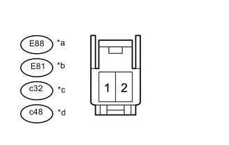
Text in Illustration *a Front view of wire harness connector
(No. 1 interior illumination light assembly RH (front footwell light))
*b Front view of wire harness connector
(No. 1 interior illumination light assembly LH (front footwell light))
*c Front view of wire harness connector
(No. 1 interior illumination light assembly RH (rear footwell light))
*d Front view of wire harness connector
(No. 1 interior illumination light assembly LH (rear footwell light))
-
Disconnect the E88 No. 1 interior illumination light assembly RH (front footwell light) connector.
-
Disconnect the E81 No. 1 interior illumination light assembly LH (front footwell light) connector.
-
Disconnect the c32 No. 1 interior illumination light assembly RH (rear footwell light) connector.
-
Disconnect the c48 No. 1 interior illumination light assembly LH (rear footwell light) connector.
-
Measure the voltage according to the value(s) in the table.
Standard Voltage Tester Connection Condition Specified Condition E88-2 (B) - Body ground Always 10.5 to 16 V E81-2 (B) - Body ground Always 10.5 to 16 V c32-2 (B) - Body ground Always 10.5 to 16 V c48-2 (B) - Body ground Always 10.5 to 16 V
NG 
CHECK COWL SIDE JUNCTION BLOCK LH Click here
OK
-
-
CHECK HARNESS AND CONNECTOR (NO. 1 INTERIOR ILLUMINATION LIGHT (FOOTWELL LIGHT) - COWL SIDE JUNCTION BLOCK LH)
-
Disconnect the E88 No. 1 interior illumination light assembly RH (front footwell light) connector.
-
Disconnect the E81 No. 1 interior illumination light assembly LH (front footwell light) connector.
-
Disconnect the c32 No. 1 interior illumination light assembly RH (rear footwell light) connector.
-
Disconnect the c48 No. 1 interior illumination light assembly LH (rear footwell light) connector.
-
Disconnect the 2J and 2K cowl side junction block LH connector.
-
Measure the resistance according to the value(s) in the table below.
Standard Resistance Tester Connection Switch Condition Specified Condition E88-1 (L) - 2J-24 Always Below 1 Ω E81-1 (L) - 2J-24 Always Below 1 Ω c32-1 (L) - 2J-24 Always Below 1 Ω c48-1 (L) - 2K-35 Always Below 1 Ω E88-1 (L) or 2J-24 - Body ground Always 10 kΩ or higher E81-1 (L) or 2J-24 - Body ground Always 10 kΩ or higher c32-1 (L) or 2J-24 - Body ground Always 10 kΩ or higher c48-1 (L) or 2K-35 - Body ground Always 10 kΩ or higher
NG
REPAIR OR REPLACE HARNESS OR CONNECTOR
OK
-
-
CHECK COWL SIDE JUNCTION BLOCK LH
-
Remove the cowl side junction block LH.
-
for LHD Click here.
-
for RHD Click here.
-
-
Remove the main body ECU (multiplex network body ECU) from the cowl side junction block LH.
-
for LHD Click here.
-
for RHD Click here.
-
-
Measure the resistance according to the value(s) in the table below.
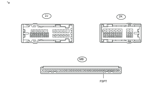
Text in Illustration *a Component without harness connected
(Cowl Side Junction Block LH)
- - Standard Resistance Tester Connection Condition Specified Condition 2J-24 - MB-26 (FSPT) Always Below 1 Ω 2K-35 - MB-26 (FSPT) Always Below 1 Ω 2J-24 or MB-26 (FSPT) - Body ground Always 10 kΩ or higher 2K-35 or MB-26 (FSPT) - Body ground Always 10 kΩ or higher Result Result Proceed to OK A NG (for LHD) B NG (for RHD) C
A
REPLACE HARNESS OR CONNECTOR (BATTERY - NO. 1 INTERIOR ILLUMINATION LIGHT (FOOTWELL LIGHT))
B
REPLACE COWL SIDE JUNCTION BLOCK LH Click here
C
REPLACE COWL SIDE JUNCTION BLOCK LH Click here
-
-
CHECK COWL SIDE JUNCTION BLOCK LH
-
Remove the cowl side junction block LH.
-
for LHD Click here.
-
for RHD Click here.
-
-
Remove the main body ECU (multiplex network body ECU) from the cowl side junction block LH.
-
for LHD Click here.
-
for RHD Click here.
-
-
Measure the resistance according to the value(s) in the table below.
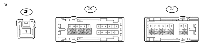
Text in Illustration *a Component without harness connected
(Cowl Side Junction Block LH)
- - Standard Resistance Tester Connection Condition Specified Condition 2F-1 - 2K-36 Always Below 1 Ω 2F-1 - 2J-9 Always Below 1 Ω 2F-1 or 2K-36 - Body ground Always 10 kΩ or higher 2F-1 or 2J-9 - Body ground Always 10 kΩ or higher Result Result Proceed to OK (for LHD) A OK (for RHD) B NG (for LHD) C NG (for RHD) D
A
REPLACE MAIN BODY ECU (MULTIPLEX NETWORK BODY ECU) Click here
B
REPLACE MAIN BODY ECU (MULTIPLEX NETWORK BODY ECU) Click here
C
REPLACE COWL SIDE JUNCTION BLOCK LH Click here
D
REPLACE COWL SIDE JUNCTION BLOCK LH Click here
-