LIGHTING SYSTEM Inside Handle Illumination Light Circuit
DESCRIPTION
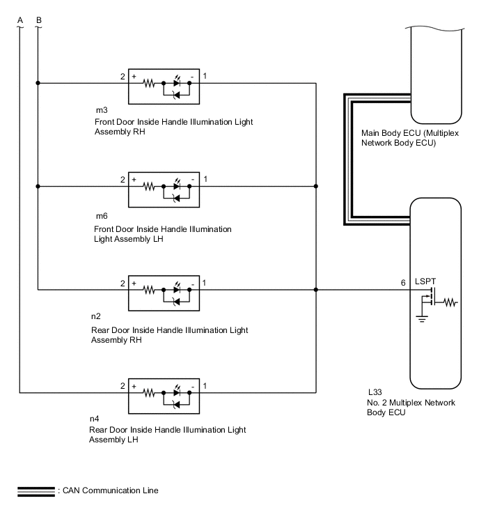
The No. 2 multiplex network body ECU controls the operation of the following lights:
-
Front door inside handle illumination light Assembly RH
-
Front door inside handle illumination light Assembly LH
-
Rear door inside handle illumination light Assembly RH
-
Rear door inside handle illumination light Assembly LH
The No. 2 multiplex network body ECU controls the door inside handle illumination lights.
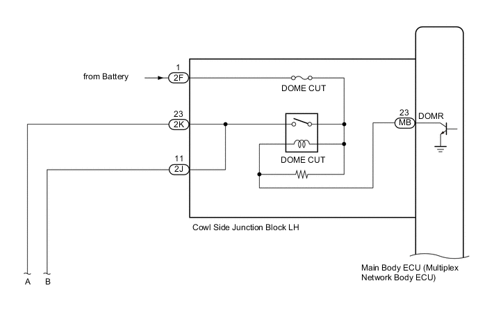
WIRING DIAGRAM
CAUTION / NOTICE / HINT
Note
-
Inspect the fuses for circuits related to this system before performing the following inspection procedure.
-
The lighting system uses CAN communication. First perform the inspections in "How to Proceed with Troubleshooting" to confirm that there are no communication malfunctions before proceeding with troubleshooting.
Tech Tips
The DOME CUT relay supplies power to the inside handle illumination lights. If all the lights that use power from the DOME CUT relay do not turn on, check the interior light auto cut circuit first Click here.
PROCEDURE
-
PERFORM ACTIVE TEST USING GTS
-
Connect the GTS to the DLC3.
-
Turn the engine switch on (IG).
-
Turn the GTS on.
-
Enter the following menus: Body Electrical / Body No. 4 / Active Test.
-
Perform the Active Test according to the display on the GTS.
Body No. 4 Tester Display Test Part Control Range Diagnostic Note Inside Handle Illumination Light Turns on the inside handle illumination lights ON/OFF - OK Inside handle illumination lights come on.
OK 
PROCEED TO NEXT SUSPECTED AREA SHOWN IN PROBLEM SYMPTOMS TABLE Click here
NG 
-
-
CHECK HARNESS OR CONNECTOR
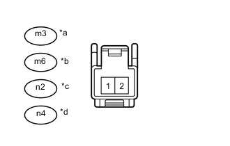
Text in Illustration *a Front view of wire harness connector
(Front Door Inside Handle Illumination Light Assembly RH)
*b Front view of wire harness connector
(Front Door Inside Handle Illumination Light Assembly LH)
*c Front view of wire harness connector
(Rear Door Inside Handle Illumination Light Assembly RH)
*d Front view of wire harness connector
(Rear Door Inside Handle Illumination Light Assembly LH)
-
Disconnect the m3 front door inside handle illumination light Assembly RH connector.
-
Disconnect the m6 front door inside handle illumination light Assembly LH connector.
-
Disconnect the n2 rear door inside handle illumination light Assembly RH connector.
-
Disconnect the n4 rear door inside handle illumination light Assembly LH connector.
-
Measure the voltage according to the value(s) in the table.
Standard Voltage Tester Connection Condition Specified Condition m3-2 (B) - Body ground Always 10.5 to 16 V m6-2 (B) - Body ground Always 10.5 to 16 V n2-2 (B) - Body ground Always 10.5 to 16 V n4-2 (B) - Body ground Always 10.5 to 16 V
NG
REPAIR OR REPLACE HARNESS OR CONNECTOR
OK
-
-
CHECK FRONT DOOR INSIDE HANDLE ILLUMINATION LAMP ASSEMBLY RH
-
Remove the door inside handle illumination light Assembly.
-
Front door inside handle illumination light Assembly RH and LH Click here.
-
Rear door inside handle illumination light Assembly RH and LH Click here.
-
-
Inspect the door inside handle illumination light Assembly.
-
Front door inside handle illumination light Assembly RH and LH Click here.
-
Rear door inside handle illumination light Assembly RH and LH Click here.
Result Result Proceed to OK A NG (Front Door Inside Handle Illumination Light Assembly RH) B NG (Front Door Inside Handle Illumination Light Assembly LH) C NG (Rear Door Inside Handle Illumination Light Assembly RH) D NG (Rear Door Inside Handle Illumination Light Assembly LH) E
-
B
REPLACE FRONT DOOR INSIDE HANDLE ILLUMINATION LAMP ASSEMBLY RH Click here
C
REPLACE FRONT DOOR INSIDE HANDLE ILLUMINATION LAMP ASSEMBLY LH Click here
D
REPLACE REAR DOOR INSIDE HANDLE ILLUMINATION LAMP ASSEMBLY RH Click here
E
REPLACE REAR DOOR INSIDE HANDLE ILLUMINATION LAMP ASSEMBLY LH Click here
A
-
-
CHECK AND REPLACE HARNESS OR CONNECTOR
-
Disconnect the m3 front door inside handle illumination light Assembly RH connector.
-
Disconnect the m6 front door inside handle illumination light Assembly LH connector.
-
Disconnect the n2 rear door inside handle illumination light Assembly RH connector.
-
Disconnect the n4 rear door inside handle illumination light Assembly LH connector.
-
Disconnect the L33 No. 2 multiplex network body ECU connector.
-
Measure the resistance according to the value(s) in the table below.
Standard Resistance Tester Connection Switch Condition Specified Condition m3-1 (-) - L33-6 (LSPT) Always Below 1 Ω m6-1 (-) - L33-6 (LSPT) Always Below 1 Ω n2-1 (-) - L33-6 (LSPT) Always Below 1 Ω n4-1 (-) - L33-6 (LSPT) Always Below 1 Ω m3-1 (-) or L33-6 (LSPT) - Body ground Always 10 kΩ or higher m6-1 (-) or L33-6 (LSPT) - Body ground Always 10 kΩ or higher n2-1 (-) or L33-6 (LSPT) - Body ground Always 10 kΩ or higher n4-1 (-) or L33-6 (LSPT) - Body ground Always 10 kΩ or higher
OK
REPLACE NO. 2 MULTIPLEX NETWORK BODY ECU Click here
NG
REPAIR OR REPLACE HARNESS OR CONNECTOR
-