LIGHTING SYSTEM Interior Light Circuit
DESCRIPTION
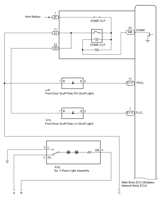
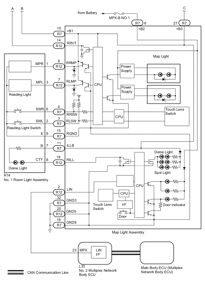
The main body ECU (multiplex network body ECU) controls the operation of the following lights:
-
Map light assembly
-
No. 1 room light assembly
-
No. 3 room light assembly
-
Front door scuff plate LH (scuff light)
-
Front door scuff plate RH (scuff light)
WIRING DIAGRAM
CAUTION / NOTICE / HINT
Note
-
Inspect the fuses for circuits related to this system before performing the following inspection procedure.
-
The lighting system uses CAN communication. First perform the inspections in "How to Proceed with Troubleshooting" to confirm that there are no communication malfunctions before proceeding with troubleshooting.
Tech Tips
The DOME CUT relay supplies power to the interior lights. If all the lights that use power from the DOME CUT relay do not turn on, check the interior light auto cut circuit first Click here.
PROCEDURE
-
PERFORM ACTIVE TEST USING GTS
-
Connect the GTS to the DLC3.
-
Turn the engine switch on (IG).
-
Turn the GTS on.
-
Enter the following menus: Body Electrical / Main Body / Active Test.
-
Check that the interior lights operate.
Main Body Tester Display Test Part Control Range Diagnostic Note Illuminated Entry System Turns on the lights that are controlled by the illuminated entry system ON/OFF Perform the Active Test with the door switch in the map light assembly turned on. OK Interior lights come on.
OK 
PROCEED TO NEXT SUSPECTED AREA SHOWN IN PROBLEM SYMPTOMS TABLE Click here
NG 
-
-
CHECK HARNESS AND CONNECTOR (MAP LIGHT ASSEMBLY - NO. 2 MULTIPLEX NETWORK BODY ECU)
-
Disconnect the R12 map light assembly connector.
-
Disconnect the L33 No. 2 multiplex network body ECU connector.
-
Measure the voltage according to the value(s) in the table below.
Standard Voltage Tester Connection Condition Specified Condition R12-2 (LIN) - L33-23 (MPX) Always Below 1 Ω R12-2 (LIN) or L33-23 (MPX) - Body ground Always 10 kΩ or higher
OK
REPLACE NO. 2 MULTIPLEX NETWORK BODY ECU Click here
NG
REPAIR OR REPLACE HARNESS OR CONNECTOR
-