LIGHTING SYSTEM IG Signal Circuit
DESCRIPTION
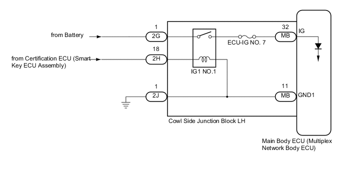
This circuit detects the engine switch on (IG) or off condition, and sends it to the main body ECU (multiplex network body ECU).
WIRING DIAGRAM
CAUTION / NOTICE / HINT
Note
-
Inspect the fuses for circuits related to this system before performing the following inspection procedure.
-
If the main body ECU (multiplex network body ECU) is replaced, refer to Service Bulletin.
-
As the door control battery is installed between the vehicle battery and main body ECU (multiplex network body ECU), first perform the inspections in On-vehicle Inspection to confirm that there are no malfunctions in the power source circuit for the main body ECU (multiplex network body ECU) before performing this troubleshooting procedure Click here.
PROCEDURE
-
CHECK FOR DTC (ENTRY AND START SYSTEM (FOR START FUNCTION))
-
Clear the DTCs Click here.
-
Check for DTCs Click here.
Result Result Proceed to Entry and Start System (for Start Function) DTCs are not output A Entry and Start System (for Start Function) DTCs are output B
B 
GO TO ENTRY AND START SYSTEM Click here
A 
-
-
READ VALUE USING GTS (IG SW)
-
Connect the GTS to the DLC3.
-
Turn the engine switch on (IG).
-
Turn the GTS on.
-
Enter the following menus: Body Electrical / Main Body / Data List.
-
Read the Data List according to the display on the GTS.
Main Body Tester Display Measurement Item/Range Normal Condition Diagnostic Note IG SW Engine switch on (IG) signal/
ON or OFF
ON: Engine switch on (IG)
OFF: Engine switch off
"OFF" is also displayed for this item when the engine switch is on (ACC). OK Normal conditions listed above are displayed.
OK
PROCEED TO NEXT SUSPECTED AREA SHOWN IN PROBLEM SYMPTOMS TABLE Click here
NG
-
-
CHECK HARNESS AND CONNECTOR (BATTERY - COWL SIDE JUNCTION BLOCK LH)
-
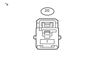
Text in Illustration *a Front view of wire harness connector
(to Cowl Side Junction Block LH)
Disconnect the 2G cowl side junction block LH connector.
-
Measure the voltage according to the value(s) in the table below.
Standard Voltage Tester Connection Switch Condition Specified Condition 2G-1 - Body ground Always 11 to 14 V
NG
REPAIR OR REPLACE HARNESS OR CONNECTOR
OK
-
-
CHECK COWL SIDE JUNCTION BLOCK LH (IG1 NO. 1 RELAY)
-
Remove the cowl side junction block LH.
-
for LHD Click here.
-
for RHD Click here.
-
-
Remove the main body ECU (multiplex network body ECU) from the cowl side junction block LH.
-
for LHD Click here.
-
for RHD Click here.
-
-
Measure the resistance according to the value(s) in the table below.
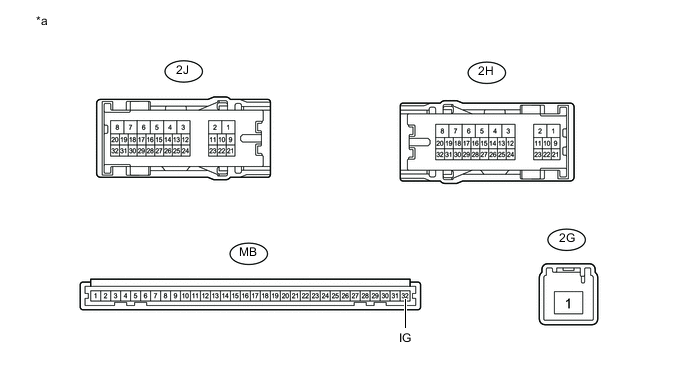
Text in Illustration *a Component without harness connected
(Cowl Side Junction Block LH)
- - Standard Resistance Tester Connection Condition Specified Condition 2H-1 - MB-32 (IG) Battery not connected to 2J-18 and 2J-1 10 kΩ or higher 2H-1 - MB-32 (IG) battery positive (+) → 2J-18
battery negative (-) → 2J-1
Below 1 Ω Result Result Proceed to OK (for LHD) A OK (for RHD) B NG (for LHD) C NG (for RHD) D
A
REPLACE MAIN BODY ECU (MULTIPLEX NETWORK BODY ECU) Click here
B
REPLACE MAIN BODY ECU (MULTIPLEX NETWORK BODY ECU) Click here
C
REPLACE COWL SIDE JUNCTION BLOCK LH Click here
D
REPLACE COWL SIDE JUNCTION BLOCK LH Click here
-