LIGHTING SYSTEM TERMINALS OF ECU
-
CHECK COWL SIDE JUNCTION BLOCK LH, MAIN BODY ECU (MULTIPLEX NET WORK BODY ECU)
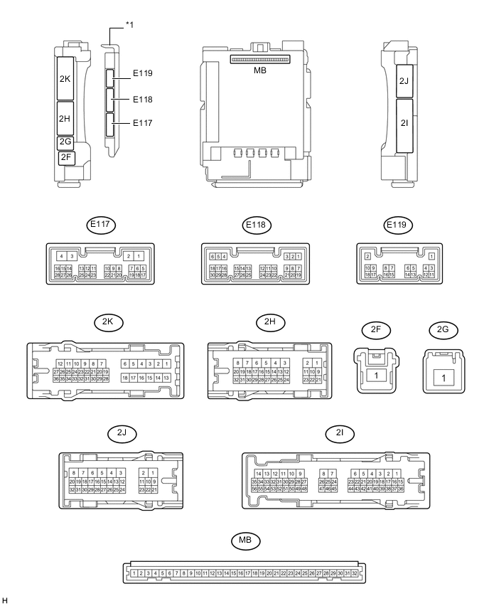
Text in Illustration *1 Main Body ECU (Multiplex Network Body ECU) - -
-
Remove the main body ECU (multiplex network body ECU) from the cowl side junction block LH assembly.
-
Disconnect the cowl side junction block LH assembly connectors.
-
Measure the voltage and resistance according to the value(s) in the table below.
Terminal No. (Symbol) Wiring Color Terminal Description Condition Specified Condition 2G-1 - Body ground W - Body ground Battery power supply Always 11 to 14 V 2F-1 - Body ground W - Body ground Battery power supply Always 11 to 14 V 2J-23 - Body ground SB - Body ground Power supply Engine switch on (IG) 11 to 14 V 2J-1 (GND) - Body ground W-B - Body ground Ground Always Below 1 V -
Reconnect the the cowl side junction block LH assembly connectors.
-
Measure the voltage and resistance according to the value(s) in the table below.
Terminal No. (Symbol) Wiring Color Terminal Description Condition Specified Condition E118-27 (FRCY) - Body ground V - Body ground Front door courtesy light switch RH signal Front door RH open Below 1 Ω Front door RH closed 10 kΩ or higher E118-6 (FLCY) - Body ground V - Body ground Front door courtesy light switch LH signal Front door LH open Below 1 Ω Front door LH closed 10 kΩ or higher 2J-29 - Body ground BE - Body ground Rear door courtesy light switch RH signal Rear door RH open Below 1 Ω Rear door RH closed 10 kΩ or higher 2K-34 - Body ground BE - Body ground Rear door courtesy light switch LH signal Rear door LH open Below 1 Ω Rear door LH closed 10 kΩ or higher 2J-16 - Body ground B - Body ground Front door unlock detection switch RH signal Front door RH unlocked Below 1 V Engine switch off, all doors closed and front door RH locked Pulse generation 2J-19 - Body ground G - Body ground Front door unlock detection switch LH signal Front door LH unlocked Below 1 V Engine switch off, all doors closed and front door LH locked Pulse generation E117-2 (LSWR) - Body ground W - Body ground Rear door unlock detection switch RH signal Rear door RH unlocked Below 1 V Engine switch off, all doors closed and rear door RH locked Pulse generation 2K-33 - Body ground L - Body ground Rear door unlock detection switch LH signal Rear door LH unlocked Below 1 V Engine switch off, all doors closed and rear door LH locked Pulse generation 2K-31 - Body ground W - Body ground Back door courtesy switch signal Back door LH open Below 1 Ω Back door LH closed 10 kΩ or higher E117-21 (LED1) - Body ground L - Body ground Door illumination light signal Door illumination light on Below 2.2 V Door illumination light off 10.5 to 16 V MB-23 (DOMR) - Body ground - Battery save system (interior light auto cut function) signal Battery save system (interior light auto cut function) operating 11 to 14 V Battery save system (interior light auto cut function) not operating Below 1 V 2J-24 - Body ground L - Body ground Interior illumination light signal Interior illumination light on Below 1 V Interior illumination light off 10.5 to 16 V 2K-35 - Body ground L - Body ground Interior illumination light signal Interior illumination light on Below 1 V Interior illumination light off 10.5 to 16 V
-
-
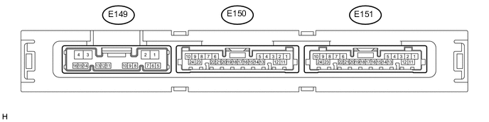
CHECK CERTIFICATION ECU (SMART KEY ECU ASSEMBLY)
-
Disconnect the E151 certification ECU connector.
-
Measure the voltage and resistance according to the value(s) in the table below.
Terminal No. (Symbol) Wiring Color Terminal Description Condition Specified Condition E151-10 (+B) - Body ground P - Body ground Battery power supply Always 11 to 14 V E151-11 (E) - Body ground BR - Body ground Ground Always Below 1 Ω -
Reconnect the E151 certification ECU connector.
-
Measure the voltage according to the value(s) in the table below.
Terminal No. (Symbol) Wiring Color Terminal Description Condition Specified Condition E151-17 (SWIL) - E151-12 (AGND) R - LG Engine switch illumination operation signal Engine switch illumination on 11 to 14 V Engine switch illumination off Below 1 V
-
-
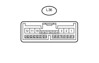
CHECK POWER BACK DOOR UNIT ASSEMBLY (MULTIPLEX NETWORK DOOR ECU)*
-
Disconnect the L36 certification ECU connector.
-
Measure the voltage and resistance according to the value(s) in the table below.
Terminal No. (Symbol) Wiring Color Terminal Description Condition Specified Condition L36-8 (IG) - Body ground G - Body ground Ignition power supply Engine switch on (IG) 11 to 14 V Engine switch off Below 1 V L36-10 (ECUB) - Body ground R - Body ground Battery power supply Always 11 to 14 V L36-12 (B) - Body ground LA-B - Body ground Battery power supply Always 11 to 14 V L36-11 (GND) - Body ground W-B - Body ground Ground Always Below 1 Ω -
Reconnect the L36 certification ECU connector.
-
Measure the voltage and resistance according to the value(s) in the table below.
Terminal No. (Symbol) Wiring Color Terminal Description Condition Specified Condition L36-20 (FUL) - Body ground W - Body ground Back door courtesy light switch signal Back door open Below 1 V Back door closed 11 to 14 V *: w/ Power Back Door
-
-
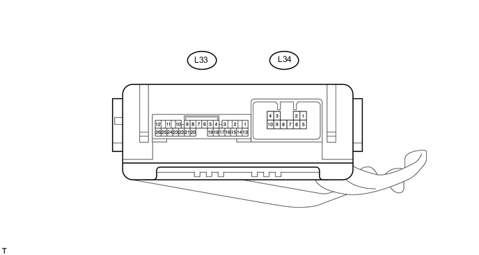
CHECK NO. 2 MULTIPLEX NETWORK BODY ECU
-
Disconnect the L33 and L34 ECU connectors.
-
Measure the voltage and resistance according to the value(s) in the table below.
Terminal No. (Symbol) Wiring Color Terminal Description Condition Specified Condition L33-14 (BECU) - Body ground R - Body ground Battery power supply Always 11 to 14 V L33-13 (SIG) - Body ground B - Body ground Ignition power supply Engine switch off Below 1 V Engine switch on (IG) 11 to 14 V L33-6 (LSPT) - Body ground L - Body ground Inside handle illumination operation signal Inside handle illumination on 11 to 14 V Inside handle illumination off Below 1 V L33-9 (RBD1) - Body ground L - Body ground Step light LH operation signal Step light LH on 11 to 14 V Step light LH off Below 1 V L33-21 (RBD2) - Body ground L - Body ground Step light RH operation signal Step light RH on 11 to 14 V Step light RH off Below 1 V L33-7 (GND) - Body ground W-B - Body ground Ground Always Below 1 Ω L34-7 (GND) - Body ground W-B - Body ground Ground Always Below 1 Ω
-
-
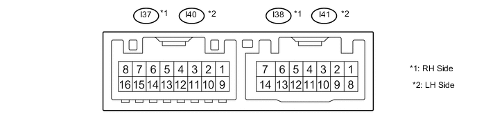
CHECK OUTER MIRROR CONTROL ECU ASSEMBLY
-
Disconnect the I37, I38, I40 and I41 outer mirror control ECU connector.
-
Measure the voltage and resistance according to the value(s) in the table below.
Terminal No. (Symbol) Wiring Color Terminal Description Condition Specified Condition I38-14 (BDR) - Body ground L - Body ground Battery power supply Always 11 to 14 V I38-5 (SIG) - Body ground B - Body ground IG power supply Engine switch off Below 1 V Engine switch on (IG) 11 to 14 V I38-7 (GND) - Body ground W-B - Body ground Ground Always Below 1 Ω I41-14 (BDR) - Body ground L - Body ground Battery power supply Always 11 to 14 V I41-5 (SIG) - Body ground B - Body ground IG power supply Engine switch off Below 1 V Engine switch on (IG) 11 to 14 V I41-7 (GND) - Body ground W-B - Body ground Ground Always Below 1 Ω -
Reconnect the I37, I38, I40 and I41 outer mirror control ECU connector.
-
Measure the voltage and resistance according to the value(s) in the table below.
Terminal No. (Symbol) Wiring Color Terminal Description Condition Specified Condition I37-2 (LP) - I37-14 (RE1) B - R Door mirror foot light RH operation signal Door mirror foot light RH off Below 1 V Door mirror foot light RH on 11 to 14 V I40-2 (LP) - I40-14 (LE1) B - LG Door mirror foot light LH operation signal Door mirror foot light LH off Below 1 V Door mirror foot light LH on 11 to 14 V
-