ROOM LIGHT(for Front) ON-VEHICLE INSPECTION
PROCEDURE
-
INSPECT MAP LIGHT ASSEMBLY
-
Remove the map light with the connector connected.
-
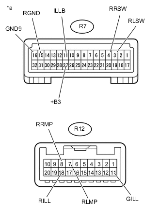
Text in Illustration *a Component with harness connected
(Map Light Assembly)
Measure the voltage according to the value(s) in the table below.
Standard Voltage Tester Connection Condition Specified Condition R7-27 (+B3) - R7-16 (GND9) Battery save system (interior light auto cut function) operating → Battery save system (interior light auto cut function) not operating 11 to 14 V → Below 1 V R7-11 (ILLB) - R7-16 (GND9) 11 to 14 V → Below 1 V R12-11 (GILL) - R7-16 (GND9) Light control switch tail 11 to 14 V R12-18 (RILL) - R7-16 (GND9) No. 1 room light on → off 11 to 14 V → Below 1 V R12-7 (RLMP) - R7-15 (RGND) Rear reading light on 11 to 14 V → Below 1 V R12-8 (RRMP) - R7-15 (RGND) Rear reading light on 11 to 14 V → Below 1 V R7-3 (RLSW) - R7-15 (RGND) Rear reading light on 5 V R7-4 (RRSW) - R7-15 (RGND) Rear reading light on 5 V If the result is not as specified, replace the map light assembly.
-
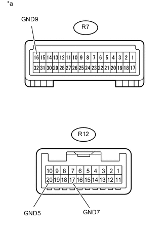
Text in Illustration *a Component with harness connected
(Map Light Assembly)
Measure the resistance according to the value(s) in the table below.
Standard Resistance Tester Connection Condition Specified Condition R7-16 (GND9) - Body ground Always Below 1 Ω R12-17 (GND7) - Body ground Always Below 1 Ω R12-20 (GND5) - Body ground Always Below 1 Ω If the result is not as specified, replace the map light assembly.
-