ENTRY AND START SYSTEM(for Start Function) Engine does not Start
DESCRIPTION
When the electrical key transmitter sub-assembly is in the cabin and the engine switch is pressed, the certification ECU (smart key ECU assembly) receives a signal and changes the power source mode. In addition, when the shift lever is in P is depressed, the engine can be started by pressing the engine switch. If the steering is unlocked, the engine can also be started by pressing the engine switch with the shift lever in N and the brake pedal depressed.
Tech Tips
-
When the certification ECU (smart key ECU assembly) is replaced with a new one and the cable is connected to the negative (-) battery terminal, the power source mode changes to on (IG).
-
When the battery cable is disconnected and reconnected, the power source returns to the mode it was in before the battery cable was disconnected.
| Problem Symptom | Data List Item | Active Test Item |
|---|---|---|
| Engine does not start |
Power Source Control
Entry&Start
Starting Control |
- |
CAUTION / NOTICE / HINT
Note
-
When using the GTS with the engine switch off, connect the GTS to the DLC3 and turn a courtesy light switch on and off at intervals of 1.5 seconds or less until communication between the GTS and the vehicle begins. Then select the vehicle type under manual mode and enter the following menus:
Body Electrical / Entry&Start. While using the GTS, periodically turn a courtesy light switch on and off at intervals of 1.5 seconds or less to maintain communication between the GTS and the vehicle.
-
The entry and start system (for Start Function) uses a multiplex communication system (LIN communication system) and the CAN communication system. Inspect the communication function by following How to Proceed with Troubleshooting Click here. Troubleshoot the entry and start system (for Start Function) after confirming that the communication systems are functioning properly.
-
If the entry and start system is disabled through the customize function, enable the system before performing troubleshooting Click here.
-
Before replacing the certification ECU (smart key ECU assembly), steering lock ECU (steering lock actuator assembly), ECM or ID code box (immobiliser code ECU), refer to the entry and start system (for Start Function) precaution Click here.
-
Inspect the fuses of circuits related to this system before performing the following inspection procedure.
-
If the steering lock ECU (steering lock actuator assembly) is replaced, be sure to confirm that the steering is unlocked by turning the steering wheel to the left and right before starting the engine. If the steering is locked for any reason, open and close a door with the engine switch off, and then unlock the steering by pressing the engine switch. This prevents the engine from starting while the steering is locked.
-
After completing repairs, confirm that the problem does not occur.
Tech Tips
If the brake pedal is repeatedly depressed while the engine is stopped, the brake booster pressure is released and the force required to depress the brake pedal to illuminate the stop lights increases.
PROCEDURE
-
CHECK ELECTRICAL KEY TRANSMITTER SUB-ASSEMBLY
-
Press a switch of the electrical key transmitter sub-assembly.
OK The electrical key transmitter sub-assembly LED illuminates.
NG 
INSPECT TRANSMITTER BATTERY Click here
OK 
-
-
READ VALUE USING GTS (KEY LOW BATTERY)
-
Connect the GTS to the DLC3.
-
Turn the engine switch on (IG).
-
Turn the GTS on.
-
Enter the following menus: Body Electrical / Entry&Start / Data List.
-
According to the display on the GTS, read the Data List.
Entry&Start Tester Display Measurement Item/Range Normal Condition Diagnostic Note Key Low Battery Transmitter battery depleted/Yes or No Yes: Transmitter battery depleted
No: Transmitter battery not depleted
The electrical key transmitter sub-assembly sends voltage information to the certification ECU (smart key ECU assembly) when it is transmitting. The certification ECU (smart key ECU assembly) displays "Yes" for the "Key Low Battery" item of the Data List when this voltage information indicates 2.2 V or less.
This Data List item should be checked when the electrical key transmitter sub-assembly is at room temperature (example: at -20°C (-4°F), "Yes" may be displayed even if the transmitter battery is new).
OK "No" is displayed in the Data List.
NG 
REPLACE TRANSMITTER BATTERY Click here
OK
-
-
CHECK WAVE ENVIRONMENT
-
If the problem occurs in certain locations or times of day, the possibility of wave interference is high.
Tech Tips
Whether the problem is due to wave interference can be checked by holding the electrical key transmitter sub-assembly near the door control receiver.
OK Engine starts.
OK
AFFECTED BY WAVE INTERFERENCE
NG
-
-
CHECK ENGINE SWITCH CONDITION
-
Get into the vehicle while carrying an electrical key transmitter sub-assembly.
-
Move the shift lever to P.
-
With the brake pedal released, check that pressing the engine switch causes the power source mode to change.
Result Result Proceed to Off → on (ACC) → on (IG) → off A Power source mode does not change to on (ACC) and on (IG) B Power source mode changes to on (IG) but not to on (ACC) C Power source mode changes to on (ACC) but not to on (IG) D
B
GO TO POWER SOURCE MODE DOES NOT CHANGE TO ON (IG AND ACC) Click here
C
GO TO POWER SOURCE MODE DOES NOT CHANGE TO ON (ACC) Click here
D
GO TO POWER SOURCE MODE DOES NOT CHANGE TO ON (IG) Click here
A
-
-
READ VALUE USING GTS (NEUTRAL SW/ CLUTCH SW, SHIFT POSITION P OR N)
-
Connect the GTS to the DLC3.
-
Turn the engine switch on (IG).
-
Turn the GTS on.
-
Enter the following menus: Body Electrical / Power Source Control or Starting Control / Data List.
-
According to the display on the GTS, read the Data List.
Power Source Control Tester Display Measurement Item/Range Normal Condition Diagnostic Note Neutral SW/ Clutch SW Shift position (P and N)/ON or OFF ON: Shift lever in P or N
OFF: Shift lever in any position other than P or N
-
Use this item to determine whether the park/neutral position switch is malfunctioning.
-
When the engine cannot be started due to a park/neutral position switch malfunction, OFF is displayed.
Starting Control Tester Display Measurement Item/Range Normal Condition Diagnostic Note Shift Position P or N Park/neutral position switch status/ON or OFF ON: Shift lever in P or N
OFF: Shift lever in any position other than P or N
When malfunctioning, the engine will not crank. OK The item in the Data List changes according to the shift position. -
NG
INSPECT PARK/NEUTRAL POSITION SWITCH ASSEMBLY Click here
OK
-
-
CHECK FOR DTC
-
Using the GTS, check for DTCs.
Result Result Proceed to DTCs are not output A Entry and start system (for Start Function) DTCs are output B
NG
DIAGNOSTIC TROUBLE CODE CHART Click here
OK
-
-
READ VALUE USING GTS (STOP LIGHT SWITCH1)
-
Connect the GTS to the DLC3.
-
Turn the engine switch on (IG).
-
Turn the GTS on.
-
Enter the following menus: Body Electrical / Power Source Control / Data List.
-
According to the display on the GTS, read the Data List.
Power Source Control Tester Display Measurement Item/Range Normal Condition Diagnostic Note Stop Light Switch1 State of brake pedal/ON or OFF ON: Brake pedal depressed
OFF: Brake pedal released
-
Use this item to determine whether the stop light switch is malfunctioning.
-
The engine cannot be started when this item is OFF.
-
When this item is malfunctioning, the engine can be started by pressing and holding the engine switch for a certain period of time.
OK The item in the Data List changes when the brake pedal is depressed and released. -
NG
CHECK HARNESS AND CONNECTOR (CERTIFICATION ECU (SMART KEY ECU ASSEMBLY) - STOP LIGHT SWITCH ASSEMBLY) Click here
OK
-
-
READ VALUE USING GTS (STARTER REQUEST SIGNAL)
-
Connect the GTS to the DLC3.
-
Turn the engine switch on (IG).
-
Turn the GTS on.
-
Enter the following menus: Body Electrical / Power Source Control / Data List.
-
According to the display on the GTS, read the Data List.
Power Source Control Tester Display Measurement Item/Range Normal Condition Diagnostic Note Starter Request Signal Engine start request signal status/ON or OFF ON: With the shift lever in P and brake pedal depressed, the engine switch is pressed and held
OFF: After approximately 1 second. has elapsed, the engine switch is released
-
When the engine cannot be started due to a start request signal malfunction, OFF is displayed.
-
When the engine switch is pressed, the duration of time that ON is displayed will be extremely short. As such, the engine switch needs to be pressed and held for a certain amount of time.
Note
Check that the key warning light is displayed on the multi-information display on the combination meter assembly, and then press the engine switch.
OK The display changes in response to the operation of the engine switch. -
NG
READ VALUE USING GTS (STARTER SW) Click here
OK
-
-
CHECK STEERING LOCK SYSTEM
-
Check that the steering unlocks when the engine switch is turned on (ACC).
OK The steering unlocks.
NG
GO TO STEERING LOCK SYSTEM (PROBLEM SYMPTOMS TABLE) Click here
OK
-
-
CHECK SECURITY INDICATOR LIGHT (IMMOBILISER SYSTEM UNSET)
-
Get into the vehicle while carrying an electrical key transmitter sub-assembly.
-
Move the shift lever to P.
-
Press the engine switch with the brake pedal released and check that the security indicator light changes from blinking to off at the same time that the power source mode changes to on (ACC).
Tech Tips
It is determined that the immobiliser function is operating correctly if the security indicator light changes from blinking to off at the same time that the power source mode changes to on (ACC).
OK Security indicator light changes from blinking to off at the same time that the power source mode changes to on (ACC).
OK
REPLACE CERTIFICATION ECU (SMART KEY ECU ASSEMBLY)
NG
GO TO IMMOBILISER SYSTEM (PROBLEM SYMPTOMS TABLE) Click here
-
-
INSPECT TRANSMITTER BATTERY
-
Inspect the transmitter battery.
Note
Do not wrap the lead wire around a terminal, wedge it between terminals, or solder it. The terminal may be deformed or damaged, and the transmitter battery will not be able to be installed correctly.
OK
REPLACE ELECTRICAL KEY TRANSMITTER SUB-ASSEMBLY
NG
REPLACE TRANSMITTER BATTERY Click here
-
-
INSPECT PARK/NEUTRAL POSITION SWITCH ASSEMBLY
-
Remove the park/neutral position switch assembly.
-
for AB60F: Click here.
-
for AE80F: Click here.
-
-
Inspect the park/neutral position switch assembly.
-
for AB60F: Click here.
-
for AE80F: Click here.
Result Result Proceed to OK A NG for AB60F B for AE80F D -
B
REPLACE PARK/NEUTRAL POSITION SWITCH ASSEMBLY Click here
C
REPLACE PARK/NEUTRAL POSITION SWITCH ASSEMBLY Click here
A
-
-
CHECK HARNESS AND CONNECTOR (CERTIFICATION ECU (SMART KEY ECU ASSEMBLY) - PARK/NEUTRAL POSITION SWITCH)
-
Disconnect the E149 certification ECU (smart key ECU assembly) connector.
-
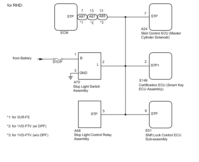
for RHD:
Disconnect the C54*1, C138*2 or C110*3 ECM connector.
-
*1: for 3UR-FE
-
*2: for 1VD-FTV (w/ DPF)
-
*3: for 1VD-FTV (w/o DPF)
-
-
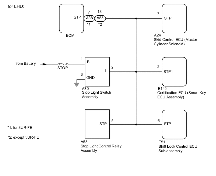
for LHD:
Disconnect the C53*1 or C110*2 ECM connector.
-
*1: for 3UR-FE
-
*2: except 3UR-FE
-
-
Disconnect the C19 park/neutral position switch assembly connector.
-
Measure the resistance according to the value(s) in the table below.
Standard Resistance for 3UR-FE Tester Connection Condition Specified Condition E149-10 (STAR) - C19-3 (B) Always Below 1 Ω E149-10 (STAR) or C19-3 (B) - Body ground 10 kΩ or higher except 3UR-FE Tester Connection Condition Specified Condition E149-10 (STAR) - C19-4 (B) Always Below 1 Ω E149-10 (STAR) or C19-4 (B) - Body ground 10 kΩ or higher
OK
REPLACE CERTIFICATION ECU (SMART KEY ECU ASSEMBLY)
NG
REPAIR OR REPLACE HARNESS OR CONNECTOR
-
-
CHECK HARNESS AND CONNECTOR (CERTIFICATION ECU (SMART KEY ECU ASSEMBLY) - STOP LIGHT SWITCH ASSEMBLY)
-
for RHD:
Disconnect the A87*1 or A85*2 ECM connector.
-
*1: except 1VD-FTV (w/o DPF)
-
*2: for 1VD-FTV (w/o DPF)
-
-
for LHD:
Disconnect the A38*1 or A85*2 ECM connector.
-
*1: for 3UR-FE
-
*2: except 3UR-FE
-
-
Disconnect the A24 skid control ECU (brake actuator assembly) connector.
-
Disconnect the E149 certification ECU (smart key ECU assembly) connector.
-
Disconnect the A70 stop light switch assembly connector.
-
Disconnect the E51 shift lock control ECU sub-assembly connector.
-
Disconnect the A39 stop light control relay assembly connector.
-
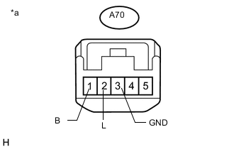
Text in Illustration *a Front view of wire harness connector
(to Stop Light Switch Assembly)
Measure the voltage according to the value(s) in the table below.
Standard Voltage Tester Connection Condition Specified Condition A70-1 (B) - Body ground Always 11 to 14 V -
Measure the resistance according to the value(s) in the table below.
Standard Resistance Tester Connection Condition Specified Condition E149-2 (STP1) - A70-2 (L) Always Below 1 Ω E149-2 (STP1) or A70-2 (L) - Body ground 10 kΩ or higher A70-3 (GND) - Body ground Below 1 Ω
NG
REPAIR OR REPLACE HARNESS OR CONNECTOR
OK
-
-
INSPECT STOP LIGHT SWITCH ASSEMBLY
-
Inspect the stop light switch assembly Click here.
OK
REPLACE CERTIFICATION ECU (SMART KEY ECU ASSEMBLY)
NG
REPLACE STOP LIGHT SWITCH ASSEMBLY Click here
-
-
READ VALUE USING GTS (STARTER SW)
-
Connect the GTS to the DLC3.
-
Turn the engine switch on (IG).
-
Turn the GTS on.
-
Enter the following menus: Body Electrical / Starting Control / Data List.
-
Get into the vehicle while carrying an electrical key transmitter sub-assembly and press the engine switch with the shift lever in P and brake pedal depressed to check if the Data List display changes.
Starting Control Tester Display Measurement Item/Range Normal Condition Diagnostic Note Starter SW Starter operation request/ON or OFF ON: Starter operation requested
OFF: Starter operation not requested
When malfunctioning, the engine will not crank. OK The Data List item changes.
NG
REPLACE CERTIFICATION ECU (SMART KEY ECU ASSEMBLY)
OK
-
-
INSPECT ST RELAY
-
Remove the ST relay.
-
Inspect the ST relay.
-
for 3UR-FE: Click here.
-
for 1VD-FTV: Click here.
-
NG
REPLACE ST RELAY
OK
-
-
CHECK HARNESS AND CONNECTOR (CERTIFICATION ECU (SMART KEY ECU ASSEMBLY) - BODY GROUND)
-
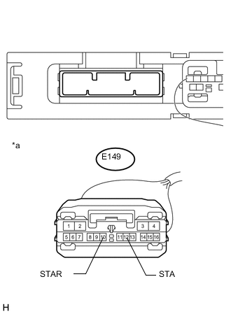
Text in Illustration *a Front view of wire harness connector
(to Certification ECU (Smart Key ECU Assembly))
Disconnect the E149 certification ECU (smart key ECU assembly) connector.
-
for RHD:
Disconnect the C54 and A87*1, C138 and A87*2 or C110 and A85*3 ECM connector.
-
*1: for 3UR-FE
-
*2: for 1VD-FTV (w/ DPF)
-
*3: for 1VD-FTV (w/o DPF)
-
-
for LHD:
Disconnect the C53 and A38*1 or C110 and A85*2 ECM connector.
-
*1: for 3UR-FE
-
*2: except 3UR-FE
-
-
Move the shift lever to P or N.
-
Measure the resistance according to the value(s) in the table below.
Standard Resistance Tester Connection Condition Specified Condition E149-10 (STAR) - Body ground 20°C (68°F) 100 to 111 Ω E149-12 (STA) - Body ground
NG
CHECK HARNESS AND CONNECTOR (CERTIFICATION ECU (SMART KEY ECU ASSEMBLY) - PARK/NEUTRAL POSITION SWITCH) Click here
OK
-
-
INSPECT STARTER ASSEMBLY
-
Remove the starter assembly.
-
for 3UR-FE: Click here.
-
for 1VD-FTV: Click here.
-
-
Inspect the starter assembly .
-
for 3UR-FE: Click here.
-
for 1VD-FTV: Click here.
Result Result Proceed to OK A NG for 3UR-FE B for 1VD-FTV C -
B
REPLACE STARTER ASSEMBLY Click here
C
REPLACE STARTER ASSEMBLY Click here
A
-
-
CHECK HARNESS AND CONNECTOR (BATTERY - STARTER AND ST RELAY )
-
Remove the starter assembly from the vehicle to perform an inspection.
-
for 3UR-FE: Click here.
-
for 1VD-FTV: Click here.
-
-
Remove the ST relay.
-
Measure the voltage according to the value(s) in the table below.
Standard Voltage for 3UR-FE Tester Connection Condition Specified Condition D3-1(B) - Body ground Always 11 to 14 V ST relay terminal 5 - Body ground except 3UR-FE Tester Connection Condition Specified Condition D12-1(B) - Body ground Always 11 to 14 V ST relay terminal 5 - Body ground -
Measure the resistance according to the value(s) in the table below.
Standard Resistance for 3UR-FE Tester Connection Condition Specified Condition ST relay terminal 3 - D2-1(ST) Always Below 1 Ω ST relay terminal 3 or D2-1(ST) - Body ground 10 kΩ or higher except 3UR-FE Tester Connection Condition Specified Condition ST relay terminal 3 - D11-1(ST) Always Below 1 Ω ST relay terminal 3 or D11-1(ST) - Body ground 10 kΩ or higher
OK
USE SIMULATION METHOD TO CHECK Click here
NG
REPAIR OR REPLACE HARNESS OR CONNECTOR
-
-
CHECK HARNESS AND CONNECTOR (CERTIFICATION ECU (SMART KEY ECU ASSEMBLY) - PARK/NEUTRAL POSITION SWITCH)
-
Disconnect the E149 certification ECU (smart key ECU assembly) connector.
-
Disconnect the C19 park/neutral position switch connector.
-
for RHD:
Disconnect the C54*1, C138*2 or C110*3 ECM connector.
-
*1: for 3UR-FE
-
*2: for 1VD-FTV (w/ DPF)
-
*3: for 1VD-FTV (w/o DPF)
-
-
for LHD:
Disconnect the C53*1 or C110*2 ECM connector.
-
*1: for 3UR-FE
-
*2: except 3UR-FE
-
-
Measure the resistance according to the value(s) in the table below.
Standard Resistance for 3UR-FE Tester Connection Condition Specified Condition E149-10 (STAR) - C19-3 (B) Always Below 1 Ω E149-10 (STAR) or C19-3 (B) - Body ground 10 kΩ or higher except 3UR-FE Tester Connection Condition Specified Condition E149-10 (STAR) - C19-4 (B) Always Below 1 Ω E149-10 (STAR) or C19-4 (B) - Body ground 10 kΩ or higher
NG
REPAIR OR REPLACE HARNESS OR CONNECTOR
OK
-
-
CHECK HARNESS AND CONNECTOR (PARK/NEUTRAL POSITION SWITCH - ST RELAY)
-
Disconnect the C19 park/neutral position switch connector.
-
Remove the ST relay.
-
Disconnect the E149 certification ECU (smart key ECU assembly) connector.
-
for RHD:
Disconnect the A87*1 or A85*2 ECM connector.
-
*1: except 1VD-FTV (w/o DPF)
-
*2: for 1VD-FTV (w/o DPF)
-
-
for LHD:
Disconnect the A38*1 or A85*2 ECM connector.
-
*1: for 3UR-FE
-
*2: except 3UR-FE
-
-
Measure the resistance according to the value(s) in the table below.
Standard Resistance for 3UR-FE Tester Connection Condition Specified Condition C19-8 (L) - ST relay terminal 2 Always Below 1 Ω C19-8 (L) or ST relay terminal 2 - Body ground 10 kΩ or higher except 3UR-FE Tester Connection Condition Specified Condition C19-5 (L) - ST relay terminal 2 Always Below 1 Ω C19-5 (L) or ST relay terminal 2 - Body ground 10 kΩ or higher
NG
REPAIR OR REPLACE HARNESS OR CONNECTOR
OK
-
-
CHECK HARNESS AND CONNECTOR (CERTIFICATION ECU (SMART KEY ECU ASSEMBLY) - ST RELAY)
-
Disconnect the E149 certification ECU (smart key ECU assembly) connector.
-
Remove the ST relay.
-
Measure the resistance according to the value(s) in the table below.
Standard Resistance Tester Connection Condition Specified Condition E149-12 (STA) - ST relay terminal 2 Always Below 1 Ω E149-12 (STA) or ST relay terminal 2 - Body ground 10 kΩ or higher
NG
REPAIR OR REPLACE HARNESS OR CONNECTOR
OK
-
-
CHECK HARNESS AND CONNECTOR (ST RELAY - BODY GROUND)
-
Remove the ST relay.
-
Measure the resistance according to the value(s) in the table below.
Standard Resistance Tester Connection Condition Specified Condition ST relay terminal 1 - Body ground Always Below 1 Ω
OK
USE SIMULATION METHOD TO CHECK Click here
NG
REPAIR OR REPLACE HARNESS OR CONNECTOR
-