THEFT DETERRENT SYSTEM Tilt Sensor Circuit
DESCRIPTION
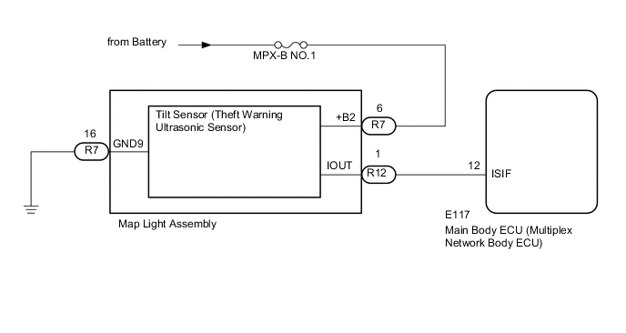
The main body ECU (multiplex network body ECU) communicates with the tilt sensor (theft warning ultrasonic sensor) via the ISIF communication line. The tilt sensor (theft warning ultrasonic sensor) sends information regarding changes in the vehicle tilt angle to the main body ECU (multiplex network body ECU). The main body ECU (multiplex network body ECU) checks whether the vehicle body is being tilted without authorization.
Tech Tips
In the following situations, the tilt sensor (theft warning ultrasonic sensor) may operate and cause the theft deterrent system to operate even when the sensor is normal.
-
The vehicle is transported by a ferry, trailer or train.
-
The vehicle is parked in a multi-story parking facility.
-
The vehicle is washed by an automatic car wash.
-
A tire blows out.
-
The vehicle is jacked up for a tire or wheel change.
-
An earthquake occurs or the road subsides.
-
Goods such as skis or snowboards are loaded or unloaded.
WIRING DIAGRAM
CAUTION / NOTICE / HINT
Note
-
If the main body ECU (multiplex network body ECU) is replaced, refer to the Service Bulletin.
-
Inspect the fuses for circuits related to this system before performing the following procedure.
-
w/ Door Control Battery:
As the door control battery is installed between the vehicle battery and main body ECU (multiplex network body ECU), first perform the inspections in On-Vehicle Inspection to confirm that there are no malfunctions in the power source circuit for the main body ECU (multiplex network body ECU) before performing this troubleshooting procedure Click here
PROCEDURE
-
READ VALUE USING GTS (Intrusion Sensor)
-
Connect the GTS to the DLC3.
-
Turn the engine switch on (IG).
-
Turn the GTS on.
-
Enter the following menus: Body Electrical / Main Body / Data List.
-
Read the Data List according to the display on the GTS.
Note
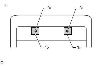
*1 Map Light Assembly *a Intrusion Sensor (Theft Warning Ultrasonic Sensor) *b Tape
-
Be sure to cover the 2 intrusion sensors (theft warning ultra sonic sensor) in the map light assembly with tape to prevent detected by the intrusion sensor.
-
After setting the theft deterrent system, wait at least 30 seconds (until the vehicle is in the armed state), tilt the vehicle (jack up the vehicle so that the tires are in the air) and check the Data List.
Tech Tips
When performing the above inspection, have the electrical key transmitter in the vehicle exterior detection area to perform certification (this prevents the alarm from sounding).
Body Electrical > Main Body > Data List Tester Display Measurement Item Range Normal Condition Diagnostic Note Intrusion Sensor Status of the tilt sensor detection ON or OFF ON: Change in pitch angle detected
OFF: Both of the conditions below is met
-
No moving object detected by sensor
-
Vehicle tilt not detected by sensor
- OK The GTS display changes correctly in response to the detection condition of the tilt sensor (theft warning ultrasonic sensor). Result Proceed to OK NG -
OK 
PROCEED TO NEXT SUSPECTED AREA SHOWN IN PROBLEM SYMPTOMS TABLE Click here
NG 
-
-
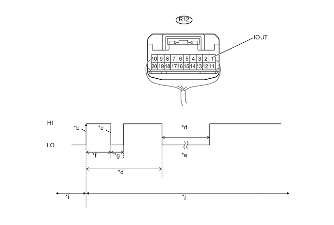
CHECK TILT SENSOR (THEFT WARNING ULTRASONIC SENSOR) (IOUT)
-
Using an oscilloscope, check the waveform.
*a Component with harness connected
(Map Light Assembly)
*b IOUT Initial Signal *c IOUT Initial Response *d Approximately 1.0 second *e Initial Diagnosis *f Approximately 1.0 to 1.6 seconds *g Approximately 0.05 seconds *h Approximately 5.5 seconds *i Disarmed State *j Arming Preparation State Measurement Condition Tester Connection Content Tester Connection R-12 (IOUT) - Body ground Tool Setting 2 V/DIV., 100 ms./DIV. Condition Theft deterrent system is set (system changes from disarmed state to arming preparation state) Tech Tips
-
If the tilt sensor (theft warning ultrasonic sensor) is normal, an initial response is output in response to the HI input from the main body ECU (multiplex network body ECU).
-
If the waveform output remains LO, there may be a problem with the main body ECU (multiplex network body ECU), as there is no input from the main body ECU (multiplex network body ECU).
OK The waveform displays properly (HI is 6.5 V or higher and LO is below 1 V). Result Proceed to OK NG (for LHD) NG (for RHD) -
NG (for LHD)
REPLACE MAIN BODY ECU (MULTIPLEX NETWORK BODY ECU) Click here
NG (for RHD)
REPLACE MAIN BODY ECU (MULTIPLEX NETWORK BODY ECU) Click here
OK
-
-
CHECK HARNESS AND CONNECTOR (MAIN BODY ECU (MULTIPLEX NETWORK BODY ECU) - MAP LIGHT ASSEMBLY)
-
Disconnect the E117 main body ECU (multiplex network body ECU) connector.
-
Disconnect the R12 map light assembly connector.
-
Measure the resistance according to the value(s) in the table below.
Standard Resistance Tester Connection Condition Specified Condition E117-12 (ISIF) - R12-1 (IOUT) Always Below 1 Ω E117-12 (ISIF) or R12-1 (IOUT) - Body ground Always 10 kΩ or higher Result Proceed to OK NG
NG
REPAIR OR REPLACE HARNESS OR CONNECTOR
OK
-
-
INSPECT MAP LIGHT ASSEMBLY
-
Remove the map light assembly.
-
Remove the tilt sensor (theft warning ultrasonic sensor) from the map light assembly.
-
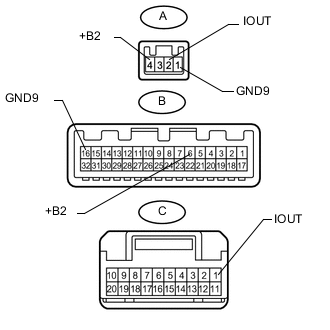
Measure the resistance according to the value(s) in the table below.
Standard Resistance Tester Connection Condition Specified Condition A-1 (GND9) -B-16 (GND9) Always Below 1 Ω A-2 (IOUT) - C-1 (IOUT) Always Below 1 Ω A-4 (+B2) - B-6 (+B2) Always 10 kΩ or higher Result Proceed to OK NG
OK
REPLACE TILT SENSOR (THEFT WARNING ULTRASONIC SENSOR) Click here
NG
REPLACE MAP LIGHT ASSEMBLY Click here
-