CAN COMMUNICATION SYSTEM(for LHD) TERMINALS OF ECU
Note
-
After turning the engine switch off, waiting time may be required before disconnecting the cable from the negative (-) battery terminal. Therefore, make sure to read the disconnecting the cable from the negative (-) battery terminal notices before proceeding with work Click here.
-
Turn the engine switch off before measuring the resistances between CAN main wires and between CAN branch wires.
-
Turn the engine switch off before inspecting CAN wires for a ground short.
-
Before measuring the resistance of the CAN bus, turn the engine switch off and leave the vehicle for 1 minute or more without operating the key, switches or opening or closing the doors. After that, disconnect the cable from the negative (-) battery terminal and leave the vehicle for 1 minute or more before measuring the resistance.
-
This section describes the standard values for all CAN related components.
Tech Tips
-
Operating the engine switch, any other switches or a door triggers related ECU and sensor communication on the CAN. This communication will cause the resistance value to change.
-
Even after DTCs are cleared, if a DTC is stored again after driving the vehicle for a while, the malfunction may be occurring due to vibration of the vehicle. In such a case, wiggling the ECUs or wire harness while performing the inspection below may help determine the cause of the malfunction.
-
JUNCTION CONNECTOR
-
NO. 1 CAN JUNCTION CONNECTOR
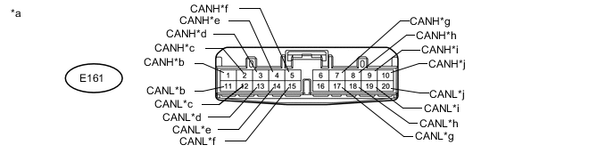
Text in Illustration *a Front view of wire harness connector
(to No. 1 CAN Junction Connector)
*b for No. 2 CAN Junction Connector *c for 4WD Control ECU *d for Power Steering ECU Assembly *e for Airbag Sensor Assembly *f for Tire Pressure Warning ECU (w/ Tire Pressure Warning System) *g for ECM *h for Air Conditioning Amplifier Assembly *i for Central Gateway ECU *j for Meter Mirror Sub-assembly (w/ Headup Display System) No. 1 CAN Junction Connector Wiring Color Connect to E161-1 (CANH) SB No. 2 CAN junction connector E161-11 (CANL) W E161-2 (CANH) P 4WD control ECU E161-12 (CANL) W E161-3 (CANH) LG Power steering ECU assembly E161-13 (CANL) W E161-4 (CANH) GR Airbag sensor assembly E161-14 (CANL) W E161-5 (CANH) R Tire pressure warning ECU*1 E161-15 (CANL) W E161-7 (CANH) V ECM E161-17 (CANL) W E161-8 (CANH) G Air conditioning amplifier assembly E161-18 (CANL) W E161-9 (CANH) L Central gateway ECU E161-19 (CANL) W E161-10 (CANH) B Meter mirror sub-assembly*2 E161-20 (CANL) W
-
*1: w/ Tire Pressure Warning System
-
*2: w/ Headup Display System
-
-
NO. 2 CAN JUNCTION CONNECTOR
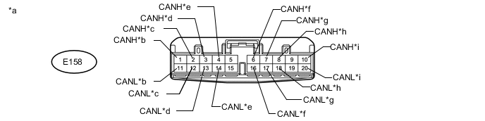
Text in Illustration *a Front view of wire harness connector
(to No. 2 CAN Junction Connector)
*b for No. 1 CAN Junction Connector *c for Main Body ECU (Multiplex Network Body ECU) *d for Master Cylinder Solenoid (Skid Control ECU) *e for Headlight ECU Sub-assembly LH *f for Certification ECU (Smart Key ECU Assembly) *g for Combination Meter Assembly *h for Steering control ECU *i for Spiral with Sensor Cable Sub-assembly (Steering Angle Sensor) - - No. 2 CAN Junction Connector Wiring Color Connect to E158-1 (CANH) SB No. 1 CAN junction connector E158-11 (CANL) W E158-2 (CANH) G Main body ECU (multiplex network body ECU) E158-12 (CANL) W E158-3 (CANH) L Master cylinder solenoid (skid control ECU) E158-13 (CANL) W E158-4 (CANH) LG Headlight ECU sub-assembly LH E158-14 (CANL) B E158-6 (CANH) B Certification ECU (smart key ECU assembly) E158-16 (CANL) W E158-7 (CANH) BE Combination meter assembly E158-17 (CANL) W E158-8 (CANH) R Steering control ECU E158-18 (CANL) W E158-10 (CANH) GR Spiral with sensor cable sub-assembly (steering angle sensor) E158-20 (CANL) W -
NO. 3 CAN JUNCTION CONNECTOR
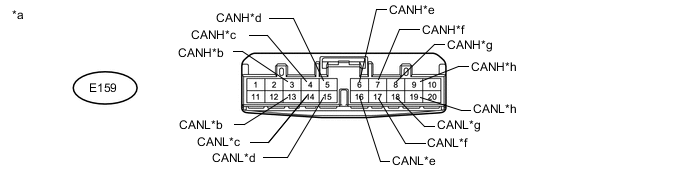
Text in Illustration *a Front view of wire harness connector
(to No. 3 CAN Junction Connector)
*b for No. 4 CAN Junction Connector *c for Driving Support ECU Assembly (w/ Pre-crash Safety System) *d for Central Gateway ECU *e for Millimeter Wave Radar Sensor Assembly (w/ Pre-crash Safety System) *f for Clearance Warning ECU Assembly *g for Parking Assist ECU *h
-
for Forward Camera Sensor (w/ Pre-crash Safety System)
-
for Inner Rear View Mirror Assembly (w/o Pre-crash Safety System)
No. 3 CAN Junction Connector Wiring Color Connect to E159-3 (CANH) W No. 4 CAN junction connector E159-13 (CANL) B E159-4 (CANH) L Driving support ECU assembly*1 E159-14 (CANL) B E159-5 (CANH) SB Central gateway ECU E159-15 (CANL) B E159-6 (CANH) L Millimeter wave radar sensor assembly*1 E159-16 (CANL) B E159-7 (CANH) V Clearance warning ECU assembly E159-17 (CANL) B E159-8 (CANH) P Parking assist ECU E159-18 (CANL) B E159-9 (CANH) G
-
Forward camera sensor*1
-
Inner rear view mirror assembly*2
E159-19 (CANL) B
-
*1: w/ Pre-crash Safety System
-
*2: w/o Pre-crash Safety System
-
-
NO. 4 CAN JUNCTION CONNECTOR
Tech Tips
Connectors that connect to the CAN junction connector can be distinguished by color of their CAN bus lines. When the connectors have been disconnected from the CAN junction connector, reconnecting the connectors to non-original positions on the CAN junction connector does not affect system performance. However, it is preferred to reconnect the connectors to their original positions to avoid negative effects on the wiring such as tension on the wiring harnesses, and to make future maintenance easier.
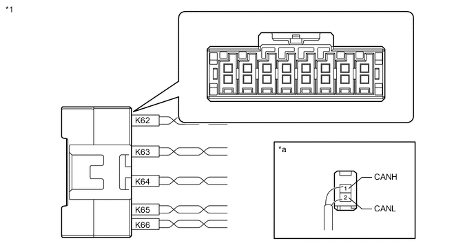
Text in Illustration *1 No. 4 CAN Junction Connector - - *a Rear view of wire harness connector
(to No. 4 CAN Junction Connector)
- - No. 4 CAN Junction Connector Wiring Color Connect to K62-1 (CANH) W No. 3 CAN junction connector K62-2 (CANL) B K63-1 (CANH) SB No. 1 CAN junction terminal K63-2 (CANL) B K64-1 (CANH) LG Parking brake ECU assembly K64-2 (CANL) B K65-1 (CANH) R Blind spot monitor sensor LH* K65-2 (CANL) B K66-1 (CANH) L Suspension control ECU K66-2 (CANL) B
-
*: w/ Blind Spot Monitor System
-
-
NO. 5 CAN JUNCTION CONNECTOR
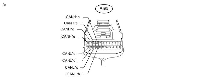
Text in Illustration *a Rear view of wire harness connector
(to No. 5 CAN Junction Connector)
*b for Central Gateway ECU *c for Bus Buffer ECU (w/ Bus Buffer ECU) *d for Multi-media Module Receiver Assembly *e for No. 6 CAN Junction Connector - - No. 5 CAN Junction Connector Wiring Color Connect to E163-8 (CANH) R Central gateway ECU E163-19 (CANL) GR E163-9 (CANH) BE Bus buffer ECU* E163-20 (CANL) GR E163-10 (CANH) G Multi-media module receiver assembly E163-21 (CANL) GR E163-11 (CANH) BE No. 6 CAN junction connector E163-22 (CANL) GR
-
*: w/ Bus Buffer ECU
-
-
NO. 6 CAN JUNCTION CONNECTOR
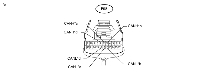
Text in Illustration *a Rear view of wire harness connector
(to No. 6 CAN Junction Connector)
*b for DCM (Telematics Transceiver) (w/ Emergency Call Switch) *c for No. 5 CAN Junction Connector *d for No. 2 CAN Junction Terminal No. 6 CAN Junction Connector Wiring Color Connect to F98-5 (CANH) L DCM (telematics transceiver)* F98-16 (CANL) GR F98-6 (CANH) BE No. 5 CAN junction connector F98-17 (CANL) GR F98-7 (CANH) B No. 2 CAN junction terminal F98-18 (CANL) GR
-
*: w/ Emergency Call Switch
-
-
NO. 7 CAN JUNCTION CONNECTOR
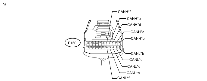
Text in Illustration *a Rear view of wire harness connector
(to No. 7 CAN Junction Connector)
*b for No. 8 CAN Junction Connector *c for Main Body ECU (Multiplex Network Body ECU) *d for Outer Mirror Control ECU Assembly LH *e for Power Seat Switch Assembly *f for Multiplex Tilt and Telescopic ECU No. 7 CAN Junction Connector Wiring Color Connect to E160-1 (CANH) W No. 8 CAN junction connector E160-12 (CANL) L E160-2 (CANH) GR Main body ECU (multiplex network body ECU) E160-13 (CANL) L E160-3 (CANH) BE Outer mirror control ECU assembly LH E160-14 (CANL) L E160-4 (CANH) V Power seat switch assembly E160-15 (CANL) L E160-5 (CANH) P Multiplex tilt and telescopic ECU E160-16 (CANL) L -
NO. 8 CAN JUNCTION CONNECTOR
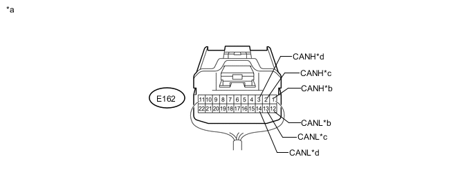
Text in Illustration *a Rear view of wire harness connector
(to No. 8 CAN Junction Connector)
*b for No. 7 CAN Junction Connector *c for No. 9 CAN Junction Connector *d for Outer Mirror Control ECU Assembly RH No. 8 CAN Junction Connector Wiring Color Connect to E162-1 (CANH) W No. 7 CAN junction connector E162-12 (CANL) L E162-2 (CANH) W No. 9 CAN junction connector E162-13 (CANL) L E162-3 (CANH) LG Outer mirror control ECU assembly RH E162-14 (CANL) L -
NO. 9 CAN JUNCTION CONNECTOR
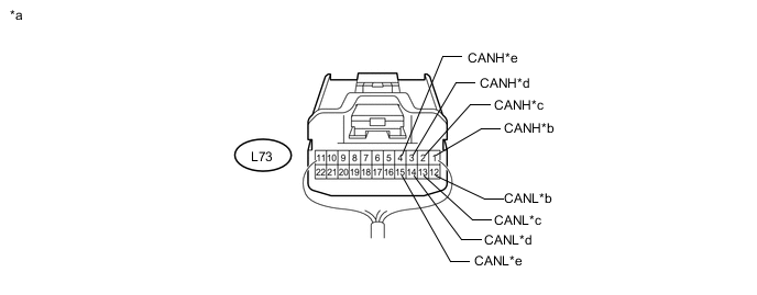
Text in Illustration *a Rear view of wire harness connector
(to No. 9 CAN Junction Connector)
*b for No. 8 CAN Junction Connector *c for No. 3 CAN Junction Terminal *d for Power Back Door Unit Assembly (Power Back Door ECU) *e for No. 2 Main Body ECU - - No. 9 CAN Junction Connector Wiring Color Connect to L73-1 (CANH) W No. 8 CAN junction connector L73-12 (CANL) L L73-2 (CANH) W No. 3 CAN junction terminal L73-13 (CANL) L L73-3 (CANH) V Power back door unit assembly (power back door ECU) L73-14 (CANL) L L73-4 (CANH) LG No. 2 main body ECU L73-15 (CANL) L -
NO. 10 CAN JUNCTION CONNECTOR (w/ Pre-crash Safety System)

Text in Illustration *a Front view of wire harness connector
(to No. 10 CAN Junction Connector)
*b for Headlight ECU Sub-assembly LH *c for Headlight ECU Sub-assembly RH *d for Millimeter Wave Radar Sensor Assembly *e for Forward Recognition Camera *f for Driving Support ECU Assembly No. 10 CAN Junction Connector Wiring Color Connect to E164-3 (CANH) L Headlight ECU Sub-assembly LH E164-13 (CANL) P E164-4 (CANH) BE Headlight ECU Sub-assembly RH E164-14 (CANL) P E164-5 (CANH) B Millimeter wave radar sensor assembly E164-15 (CANL) P E164-6 (CANH) R Forward recognition camera E164-16 (CANL) P E164-7 (CANH) W Driving support ECU assembly E164-17 (CANL) P -

Text in Illustration *a Rear view of wire harness connector
(to No. 1 CAN Junction Terminal)
NO. 1 CAN JUNCTION TERMINAL
No. 1 CAN Junction Terminal Wiring Color Connect to K57-3 (CANH) SB No. 4 CAN junction connector K57-2 (CANL) B -
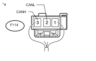
Text in Illustration *a Rear view of wire harness connector
(to No. 2 CAN Junction Terminal)
NO. 2 CAN JUNCTION TERMINAL
No. 2 CAN Junction Terminal Wiring Color Connect to F114-3 (CANH) B No. 6 CAN junction connector F114-2 (CANL) GR -
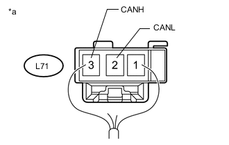
Text in Illustration *a Rear view of wire harness connector
(to No. 3 CAN Junction Terminal)
NO. 3 CAN JUNCTION TERMINAL
No. 3 CAN Junction Terminal Wiring Color Connect to L71-3 (CANH) W No. 9 CAN junction connector L71-2 (CANL) L
-
-
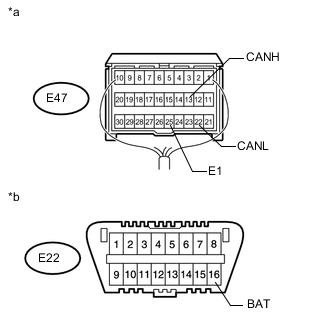
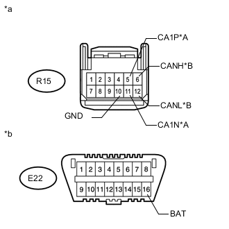
CHECK DLC3
-
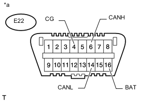
Text in Illustration *a Front view of DLC3 Disconnect the cable from the negative (-) battery terminal before measuring the resistances of the CAN main wire and CAN branch wire.
-
Measure the resistance according to the value(s) in the table below.
Terminal No. (Symbol) Wiring Color Switch Condition Specified Condition E22-6 (CANH) - E22-14 (CANL) LG - W Cable disconnected from negative (-) battery terminal 54 to 66 Ω E22-6 (CANH) - E22-4 (CG) LG - W-B Cable disconnected from negative (-) battery terminal 200 Ω or higher E22-14 (CANL) - E22-4 (CG) W - W-B Cable disconnected from negative (-) battery terminal 200 Ω or higher E22-6 (CANH) - E22-16 (BAT) LG - L Cable disconnected from negative (-) battery terminal 6 kΩ or higher E22-14 (CANL) - E22-16 (BAT) W - L Cable disconnected from negative (-) battery terminal 6 kΩ or higher
-
-
CHECK CENTRAL GATEWAY ECU
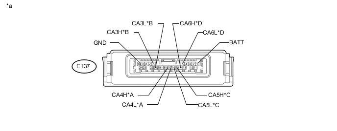
Text in Illustration *A Bus 2 *B Bus 3 *C Bus 5 *D V Bus *a Component without harness connected
(Central Gateway ECU)
- -
-
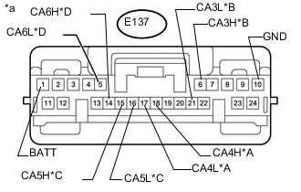
Text in Illustration *A Bus 2 *B Bus 3 *C Bus 5 *D V Bus *a Front view of wire harness connector
(to Central Gateway ECU)
Disconnect the central gateway ECU connector.
-
Measure the resistance according to the value(s) in the table below.
Bus 2 Terminal No. (Symbol) Wiring Color Switch Condition Specified Condition E137-18 (CA4H) - E137-17 (CA4L) L - W Cable disconnected from negative (-) battery terminal 54 to 69 Ω E137-18 (CA4H) - E137-10 (GND) L - BR Cable disconnected from negative (-) battery terminal 200 Ω or higher E137-17 (CA4L) - E137-10 (GND) W - BR Cable disconnected from negative (-) battery terminal 200 Ω or higher E137-18 (CA4H) - E137-1 (BATT) L - R Cable disconnected from negative (-) battery terminal 6 kΩ or higher E137-17 (CA4L) - E137-1 (BATT) W - R Cable disconnected from negative (-) battery terminal 6 kΩ or higher Bus 3 Terminal No. (Symbol) Wiring Color Switch Condition Specified Condition E137-6 (CA3H) - E137-21 (CA3L) R - GR Cable disconnected from negative (-) battery terminal 108 to 132 Ω E137-6 (CA3H) - E137-10 (GND) R - BR Cable disconnected from negative (-) battery terminal 200 Ω or higher E137-21 (CA3L) - E137-10 (GND) GR - BR Cable disconnected from negative (-) battery terminal 200 Ω or higher E137-6 (CA3H) - E137-1 (BATT) R - R Cable disconnected from negative (-) battery terminal 6 kΩ or higher E137-21 (CA3L) - E137-1 (BATT) GR - R Cable disconnected from negative (-) battery terminal 6 kΩ or higher Bus 5 Terminal No. (Symbol) Wiring Color Switch Condition Specified Condition E137-15 (CA5H) - E137-16 (CA5L) SB - B Cable disconnected from negative (-) battery terminal 108 to 132 Ω E137-15 (CA5H) - E137-10 (GND) SB - BR Cable disconnected from negative (-) battery terminal 200 Ω or higher E137-16 (CA5L) - E137-10 (GND) B - BR Cable disconnected from negative (-) battery terminal 200 Ω or higher E137-15 (CA5H) - E137-1 (BATT) SB - R Cable disconnected from negative (-) battery terminal 6 kΩ or higher E137-16 (CA5L) - E137-1 (BATT) B - R Cable disconnected from negative (-) battery terminal 6 kΩ or higher V Bus Terminal No. (Symbol) Wiring Color Switch Condition Specified Condition E137-14 (CA6H) - E137-10 (GND) LG - BR Cable disconnected from negative (-) battery terminal 200 Ω or higher E137-5 (CA6L) - E137-10 (GND) W - BR Cable disconnected from negative (-) battery terminal 200 Ω or higher E137-14 (CA6H) - E137-1 (BATT) LG - R Cable disconnected from negative (-) battery terminal 6 kΩ or higher E137-5 (CA6L) - E137-1 (BATT) W - R Cable disconnected from negative (-) battery terminal 6 kΩ or higher
-
-
CHECK ECM
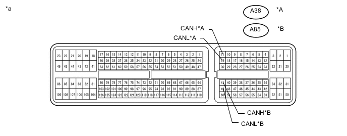
Text in Illustration *A for 3UR-FE *B for 1VD-FTV *a Component without harness connected
(ECM)
- -
-
Disconnect the ECM connectors.
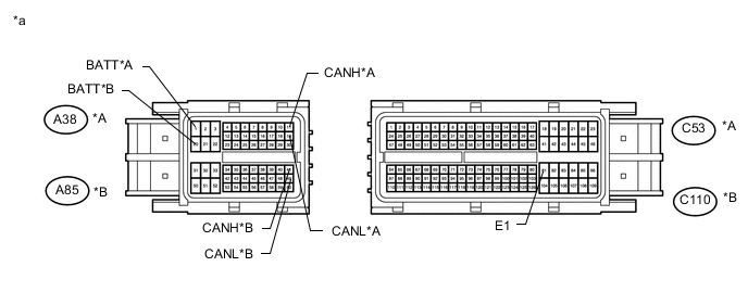
Text in Illustration *A for 3UR-FE *B for 1VD-FTV *a Front view of wire harness connector
(to ECM)
- - -
Measure the resistance according to the value(s) in the table below.
for 3UR-FE Terminal No. (Symbol) Wiring Color Switch Condition Specified Condition A38-11 (CANH) - A38-19 (CANL) V - W Cable disconnected from negative (-) battery terminal 108 to 132 Ω A38-11 (CANH) - C53-81 (E1) V - W-B Cable disconnected from negative (-) battery terminal 200 Ω or higher A38-19 (CANL) - C53-81 (E1) W - W-B Cable disconnected from negative (-) battery terminal 200 Ω or higher A38-11 (CANH) - A38-1 (BATT) V - L Cable disconnected from negative (-) battery terminal 6 kΩ or higher A38-19 (CANL) - A38-1 (BATT) W - L Cable disconnected from negative (-) battery terminal 6 kΩ or higher for 1VD-FTV Terminal No. (Symbol) Wiring Color Switch Condition Specified Condition A85-41 (CANH) - A85-49 (CANL) V - W Cable disconnected from negative (-) battery terminal 108 to 132 Ω A85-41 (CANH) - C110-81 (E1) V - BR Cable disconnected from negative (-) battery terminal 200 Ω or higher A85-49 (CANL) - C110-81 (E1) W - BR Cable disconnected from negative (-) battery terminal 200 Ω or higher A85-41 (CANH) - A85-20 (BATT) V - L Cable disconnected from negative (-) battery terminal 6 kΩ or higher A85-49 (CANL) - A85-20 (BATT) W - L Cable disconnected from negative (-) battery terminal 6 kΩ or higher
-
-
CHECK MASTER CYLINDER SOLENOID (SKID CONTROL ECU)
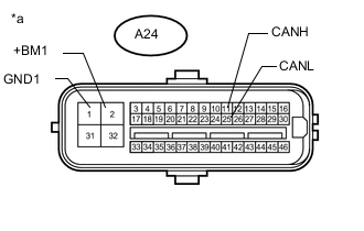
Text in Illustration *a Component without harness connected
(Master Cylinder Solenoid [Skid Control ECU])
- -
-
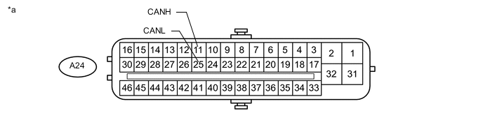
Text in Illustration *a Front view of wire harness connector
(to Master Cylinder Solenoid [Skid Control ECU])
Disconnect the master cylinder solenoid (skid control ECU) connector.
-
Measure the resistance according to the value(s) in the table below.
Terminal No. (Symbol) Wiring Color Switch Condition Specified Condition A24-11 (CANH) - A24-25 (CANL) L - W Cable disconnected from negative (-) battery terminal 54 to 69 Ω A24-11 (CANH) - A24-1 (GND1) L - W-B Cable disconnected from negative (-) battery terminal 200 Ω or higher A24-25 (CANL) - A24-1 (GND1) W - W-B Cable disconnected from negative (-) battery terminal 200 Ω or higher A24-11 (CANH) - A24-2 (+BM1) L - B Cable disconnected from negative (-) battery terminal 6 kΩ or higher A24-25 (CANL) - A24-2 (+BM1) W - B Cable disconnected from negative (-) battery terminal 6 kΩ or higher
-
-
CHECK AIR CONDITIONING AMPLIFIER ASSEMBLY
Text in Illustration *a Component without harness connected
(Air Conditioning Amplifier Assembly)
- -
-
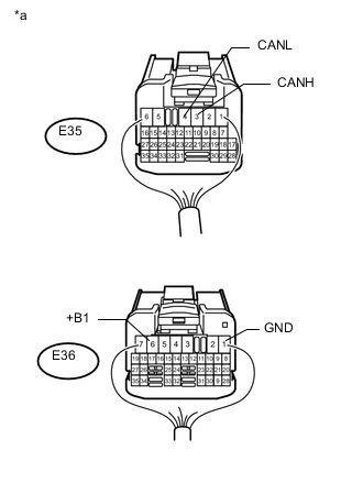
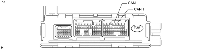
Text in Illustration *a Rear view of wire harness connector
(to Air Conditioning Amplifier Assembly)
Disconnect the air conditioning amplifier assembly connectors.
-
Measure the voltage and resistance according to the value(s) in the table below.
Terminal No. (Symbol) Wiring Color Condition Specified Condition E35-3 (CANH) - E35-4 (CANL) G - W Cable disconnected from negative (-) battery terminal 54 to 69 Ω E35-3 (CANH) - E36-1 (GND) G - BR Cable disconnected from negative (-) battery terminal 200 Ω or higher E35-4 (CANL) - E36-1 (GND) W - BR Cable disconnected from negative (-) battery terminal 200 Ω or higher E35-3 (CANH) - E36-6 (+B1) G - LG Cable disconnected from negative (-) battery terminal 6 kΩ or higher E35-4 (CANL) - E36-6 (+B1) W - LG Cable disconnected from negative (-) battery terminal 6 kΩ or higher
-
-
CHECK COWL SIDE JUNCTION BLOCK LH AND MAIN BODY ECU (MULTIPLEX NETWORK BODY ECU)
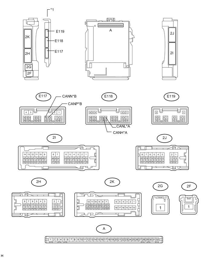
Text in Illustration *A Bus 2 *B Sub Bus 1 *1 Main Body ECU (Multiplex Network Body ECU) - -
-
Remove the main body ECU (multiplex network body ECU) from the cowl side junction block LH Click here.
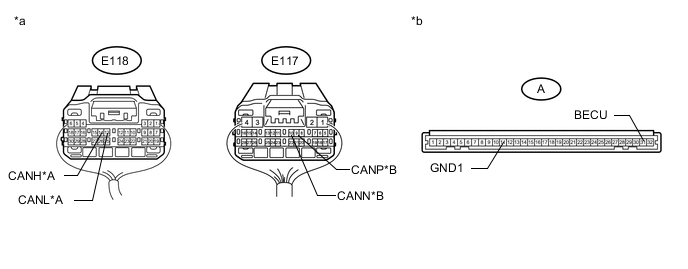
Text in Illustration *A Bus 2 *B Sub Bus 1 *1 Main Body ECU (Multiplex Network Body ECU) - - *a Rear view of wire harness connector
(to Main Body ECU [Multiplex Network Body ECU])
*b Front view of wire harness connector
(to Main Body ECU [Multiplex Network Body ECU])
-
Reconnect the cowl side junction block LH connectors.
-
Measure the resistance according to the value(s) in the table below.
Bus 2 Terminal No. (Symbol) Wiring Color Switch Condition Specified Condition E118-14 (CANH) - E118-13 (CANL) G - W Cable disconnected from negative (-) battery terminal 54 to 69 Ω E118-14 (CANH) - A-11 (GND1) G - None Cable disconnected from negative (-) battery terminal 200 Ω or higher E118-13 (CANL) - A-11 (GND1) W - None Cable disconnected from negative (-) battery terminal 200 Ω or higher E118-14 (CANH) - A-31 (BECU) G - None Cable disconnected from negative (-) battery terminal 6 kΩ or higher E118-13 (CANL) - A-31 (BECU) W - None Cable disconnected from negative (-) battery terminal 6 kΩ or higher Sub Bus 1 Terminal No. (Symbol) Wiring Color Switch Condition Specified Condition E117-9 (CANP) - E117-10 (CANN) GR - L Cable disconnected from negative (-) battery terminal 108 to 132 Ω E117-9 (CANP) - A-11 (GND1) GR - None Cable disconnected from negative (-) battery terminal 200 Ω or higher E117-10 (CANN) - A-11 (GND1) L - None Cable disconnected from negative (-) battery terminal 200 Ω or higher E117-9 (CANP) - A-31 (BECU) GR - None Cable disconnected from negative (-) battery terminal 6 kΩ or higher E117-10 (CANN) - A-31 (BECU) L - None Cable disconnected from negative (-) battery terminal 6 kΩ or higher
-
-
CHECK COMBINATION METER ASSEMBLY
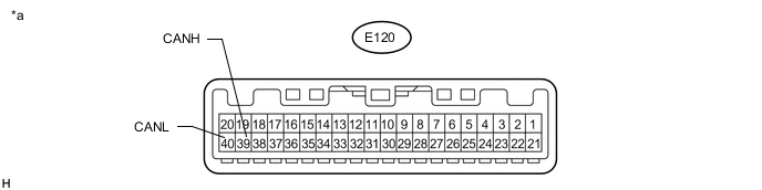
Text in Illustration *a Component without harness connected
(Combination Meter Assembly)
- -
-
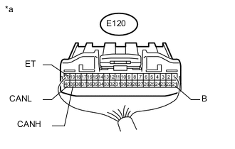
Text in Illustration *a Rear view of wire harness connector
(to Combination Meter Assembly)
Disconnect the combination meter assembly connector.
-
Measure the resistance according to the value(s) in the table below.
Terminal No. (Symbol) Wiring Color Switch Condition Specified Condition E120-39 (CANH) - E120-40 (CANL) BE - W Cable disconnected from negative (-) battery terminal 108 to 132 Ω E120-39 (CANH) - E120-20 (ET) BE - BR Cable disconnected from negative (-) battery terminal 200 Ω or higher E120-40 (CANL) - E120-20 (ET) W - BR Cable disconnected from negative (-) battery terminal 200 Ω or higher E120-39 (CANH) - E120-21 (B) BE - V Cable disconnected from negative (-) battery terminal 6 kΩ or higher E120-40 (CANL) - E120-21 (B) W - V Cable disconnected from negative (-) battery terminal 6 kΩ or higher
-
-
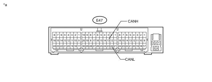
CHECK AIRBAG SENSOR ASSEMBLY
Text in Illustration *a Component without harness connected
(Airbag Sensor Assembly)
- -
-
Text in Illustration *a Rear view of wire harness connector
(to Airbag Sensor Assembly)
*b Front view of DLC3 Disconnect the airbag sensor assembly connector.
-
Measure the resistance according to the value(s) in the table below.
Terminal No. (Symbol) Wiring Color Switch Condition Specified Condition E47-13 (CANH) - E47-22 (CANL) GR - W Cable disconnected from negative (-) battery terminal 54 to 69 Ω E47-13 (CANH) - E47-25 (E1) GR - BR Cable disconnected from negative (-) battery terminal 200 Ω or higher E47-22 (CANL) - E47-25 (E1) W - BR Cable disconnected from negative (-) battery terminal 200 Ω or higher E47-13 (CANH) - E22-16 (BAT) GR - L Cable disconnected from negative (-) battery terminal 6 kΩ or higher E47-22 (CANL) - E22-16 (BAT) W - L Cable disconnected from negative (-) battery terminal 6 kΩ or higher
-
-
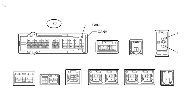
CHECK MULTI-MEDIA MODULE RECEIVER ASSEMBLY
Text in Illustration *a Component without harness connected
(Multi-media Module Receiver Assembly)
- -
-
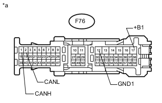
Text in Illustration *a Front view of wire harness connector
(to Multi-media Module Receiver Assembly)
Disconnect the multi-media module receiver assembly connector.
-
Measure the resistance according to the value(s) in the table below.
Terminal No. (Symbol) Wiring Color Switch Condition Specified Condition F76-1 (CANH) - F76-2 (CANL) G - GR Cable disconnected from negative (-) battery terminal 54 to 69 Ω F76-1 (CANH) - F76-12 (GND1) G - W-B Cable disconnected from negative (-) battery terminal 200 Ω or higher F76-2 (CANL) - F76-12 (GND1) GR - W-B Cable disconnected from negative (-) battery terminal 200 Ω or higher F76-1 (CANH) - F76-17 (+B1) G - V Cable disconnected from negative (-) battery terminal 6 kΩ or higher F76-2 (CANL) - F76-17 (+B1) GR - V Cable disconnected from negative (-) battery terminal 6 kΩ or higher
-
-
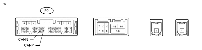
CHECK DCM (TELEMATICS TRANSCEIVER) (w/ Emergency Call Switch)
Text in Illustration *a Component without harness connected
(DCM [Telematics Transceiver]))
- -
-
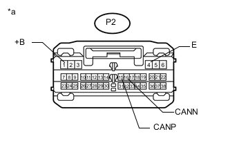
Text in Illustration *a Front view of wire harness connector
(to DCM [Telematics Transceiver])
Disconnect the DCM (telematics transceiver) connector.
-
Measure the resistance according to the value(s) in the table below.
Terminal No. (Symbol) Wiring Color Switch Condition Specified Condition P2-15 (CANP) - P2-16 (CANN) L - GR Cable disconnected from negative (-) battery terminal 54 to 69 Ω P2-15 (CANP) - P2-4 (E) L - W-B Cable disconnected from negative (-) battery terminal 200 Ω or higher P2-16 (CANN) - P2-4 (E) GR - W-B Cable disconnected from negative (-) battery terminal 200 Ω or higher P2-15 (CANP) - P24-1 (+B) L - P Cable disconnected from negative (-) battery terminal 6 kΩ or higher P2-16 (CANN) - P24-1 (+B) GR - P Cable disconnected from negative (-) battery terminal 6 kΩ or higher
-
-
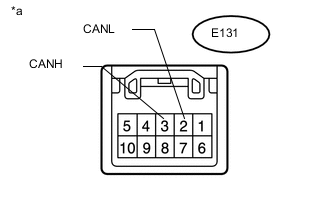
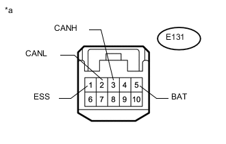
CHECK SPIRAL WITH SENSOR CABLE SUB-ASSEMBLY (STEERING ANGLE SENSOR)
Text in Illustration *a Component without harness connected
(Spiral with Sensor Cable Sub-assembly [Steering Angle Sensor])
-
Text in Illustration *a Front view of wire harness connector
(to Spiral with Sensor Cable Sub-assembly [Steering Angle Sensor])
Disconnect the spiral with sensor cable sub-assembly (steering angle sensor) connector.
-
Measure the resistance according to the value(s) in the table below.
Terminal No. (Symbol) Wiring Color Switch Condition Specified Condition E131-3 (CANH) - E131-2 (CANL) GR - W Cable disconnected from negative (-) battery terminal 54 to 69 Ω E131-3 (CANH) - E131-1 (ESS) GR - W-B Cable disconnected from negative (-) battery terminal 200 Ω or higher E131-2 (CANL) - E131-1 (ESS) W - W-B Cable disconnected from negative (-) battery terminal 200 Ω or higher E131-3 (CANH) - E131-5 (BAT) GR - R Cable disconnected from negative (-) battery terminal 6 kΩ or higher E131-2 (CANL) - E131-5 (BAT) W - R Cable disconnected from negative (-) battery terminal 6 kΩ or higher
-
-
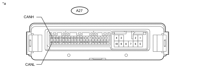
CHECK 4WD CONTROL ECU
Text in Illustration *a Component without harness connected
(4WD Control ECU)
- -
-
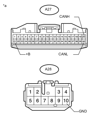
Text in Illustration *a Front view of wire harness connector
(to 4WD Control ECU)
Disconnect the 4WD control ECU connectors.
-
Measure the resistance according to the value(s) in the table below.
Terminal No. (Symbol) Wiring Color Switch Condition Specified Condition A27-20 (CANH) - A27-40 (CANL) P - W Cable disconnected from negative (-) battery terminal 54 to 69 Ω A27-20 (CANH) - A28-10 (GND) P - W-B Cable disconnected from negative (-) battery terminal 200 Ω or higher A27-40 (CANL) - A28-10 (GND) W - W-B Cable disconnected from negative (-) battery terminal 200 Ω or higher A27-20 (CANH) - A27-21 (+B) P - R Cable disconnected from negative (-) battery terminal 6 kΩ or higher A27-40 (CANL) - A27-21 (+B) W - R Cable disconnected from negative (-) battery terminal 6 kΩ or higher
-
-
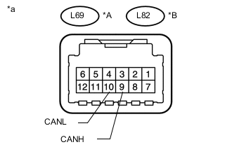
CHECK TIRE PRESSURE WARNING ECU (w/ Tire Pressure Warning System)
Text in Illustration *A w/o Front Antenna *B w/ Front Antenna *a Component without harness connected
(Tire Pressure Warning ECU)
-
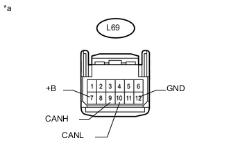
Text in Illustration *a Front view of wire harness connector
(to Tire Pressure Warning ECU)
w/o Front Antenna:
-
Disconnect the tire pressure warning ECU connector.
-
Measure the resistance according to the value(s) in the table below.
Terminal No. (Symbol) Wiring Color Switch Condition Specified Condition L69-9 (CANH) - L69-10 (CANL) R - W Cable disconnected from negative (-) battery terminal 54 to 69 Ω L69-9 (CANH) - L69-12 (GND) R - BR Cable disconnected from negative (-) battery terminal 200 Ω or higher L69-10 (CANL) - L69-12 (GND) W - BR Cable disconnected from negative (-) battery terminal 200 Ω or higher L69-9 (CANH) - L69-7 (+B) R - R Cable disconnected from negative (-) battery terminal 6 kΩ or higher L69-10 (CANL) - L69-7 (+B) W - R Cable disconnected from negative (-) battery terminal 6 kΩ or higher
-
-
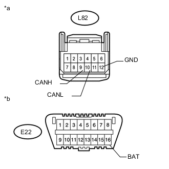
Text in Illustration *a Front view of wire harness connector
(to Tire Pressure Warning ECU)
*b Front view DLC3 w/ Front Antenna:
-
Disconnect the tire pressure warning ECU connector.
-
Measure the resistance according to the value(s) in the table below.
Terminal No. (Symbol) Wiring Color Switch Condition Specified Condition L82-9 (CANH) - L82-10 (CANL) R - W Cable disconnected from negative (-) battery terminal 54 to 69 Ω L82-9 (CANH) - L82-12 (GND) R - BR Cable disconnected from negative (-) battery terminal 200 Ω or higher L82-10 (CANL) - L82-12 (GND) W - BR Cable disconnected from negative (-) battery terminal 200 Ω or higher L82-9 (CANH) - E22-16 (BAT) R - L Cable disconnected from negative (-) battery terminal 6 kΩ or higher L82-10 (CANL) - E22-16 (BAT) W - L Cable disconnected from negative (-) battery terminal 6 kΩ or higher
-
-
-
CHECK STEERING CONTROL ECU
Text in Illustration *a Component without harness connected
(Steering Control ECU)
- -
-
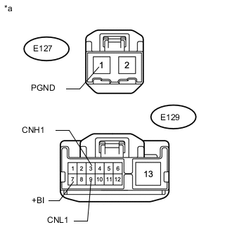
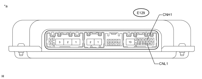
Text in Illustration *a Front view of wire harness connector
(to Steering Control ECU)
Disconnect the steering control ECU connectors.
-
Measure the resistance according to the value(s) in the table below.
Terminal No. (Symbol) Wiring Color Switch Condition Specified Condition E129-3 (CNH1) - E129-9 (CNL1) R - W Cable disconnected from negative (-) battery terminal 54 to 69 Ω E129-3 (CNH1) - E127-1 (PGND) R - W-B Cable disconnected from negative (-) battery terminal 200 Ω or higher E129-9 (CNL1) - E127-1 (PGND) W - W-B Cable disconnected from negative (-) battery terminal 200 Ω or higher E129-3 (CNH1) - E129-7 (+BI) R - R Cable disconnected from negative (-) battery terminal 6 kΩ or higher E129-9 (CNL1) - E129-7 (+BI) W - R Cable disconnected from negative (-) battery terminal 6 kΩ or higher
-
-
CHECK CERTIFICATION ECU (SMART KEY ECU ASSEMBLY)
Text in Illustration *a Component without harness connected
(Certification ECU [Smart Key ECU Assembly])
- -
-
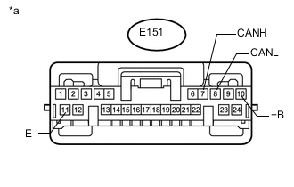
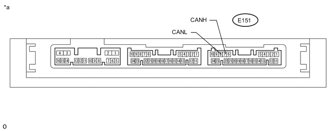
Text in Illustration *a Front view of wire harness connector
(to Certification ECU [Smart Key ECU Assembly])
Disconnect the certification ECU (smart key ECU assembly) connector.
-
Measure the resistance according to the value(s) in the table below.
Terminal No. (Symbol) Wiring Color Switch Condition Specified Condition E151-7 (CANH) - E151-8 (CANL) B - W Cable disconnected from negative (-) battery terminal 54 to 69 Ω E151-7 (CANH) - E151-11 (E) B - BR Cable disconnected from negative (-) battery terminal 200 Ω or higher E151-8 (CANL) - E151-11 (E) W - BR Cable disconnected from negative (-) battery terminal 200 Ω or higher E151-7 (CANH) - E151-10 (+B) B - P Cable disconnected from negative (-) battery terminal 6 kΩ or higher E151-8 (CANL) - E151-10 (+B) W - P Cable disconnected from negative (-) battery terminal 6 kΩ or higher
-
-
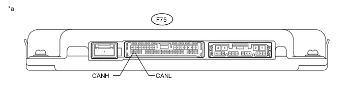
CHECK PARKING ASSIST ECU
Text in Illustration *a Component without harness connected
(Parking Assist ECU)
- -
-
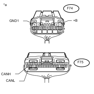
Text in Illustration *a Rear view of wire harness connector
(to Parking Assist ECU)
Disconnect the parking assist ECU connectors.
-
Measure the resistance according to the value(s) in the table below.
Terminal No. (Symbol) Wiring Color Switch Condition Specified Condition F75-40 (CANH) - F75-39 (CANL) P - B Cable disconnected from negative (-) battery terminal 54 to 69 Ω F75-40 (CANH) - F74-4 (GND1) P - W-B Cable disconnected from negative (-) battery terminal 200 Ω or higher F75-39 (CANL) - F74-4 (GND1) B - W-B Cable disconnected from negative (-) battery terminal 200 Ω or higher F75-40 (CANH) - F74-1 (+B) P - G Cable disconnected from negative (-) battery terminal 6 kΩ or higher F75-39 (CANL) - F74-1 (+B) B - G Cable disconnected from negative (-) battery terminal 6 kΩ or higher
-
-
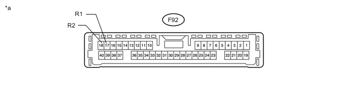
CHECK CLEARANCE WARNING ECU ASSEMBLY
Text in Illustration *a Component without harness connected
(Clearance Warning ECU Assembly)
- -
-
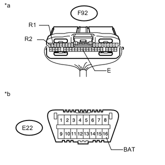
Text in Illustration *a Rear view of wire harness connector
(to Clearance Warning ECU Assembly)
*b Front view of DLC3 Disconnect the clearance warning ECU assembly connector.
-
Measure the resistance according to the value(s) in the table below.
Terminal No. (Symbol) Wiring Color Switch Condition Specified Condition F92-17 (R1) - F92-18 (R2) V - B Cable disconnected from negative (-) battery terminal 54 to 69 Ω F92-17 (R1) - F92-30 (E) V - BR Cable disconnected from negative (-) battery terminal 200 Ω or higher F92-18 (R2) - F92-30 (E) B- BR Cable disconnected from negative (-) battery terminal 200 Ω or higher F92-17 (R1) - E22-16 (BAT) V - L Cable disconnected from negative (-) battery terminal 6 kΩ or higher F92-18 (R2) - E22-16 (BAT) B- L Cable disconnected from negative (-) battery terminal 6 kΩ or higher
-
-
CHECK DRIVING SUPPORT ECU ASSEMBLY (w/ Pre-crash Safety System)
Text in Illustration *A Bus 5 *B Local Bus *a Component without harness connected
(Driving Support ECU Assembly)
- -
-
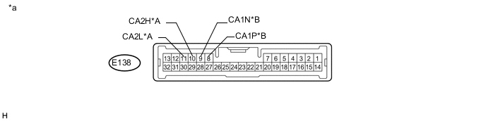
Text in Illustration *A Bus 5 *B Local Bus *a Front view of wire harness connector
(to Driving Support ECU Assembly)
*b Front view of DLC3 Disconnect the driving support ECU assembly connector.
-
Measure the resistance according to the value(s) in the table below.
Bus 5 Terminal No. (Symbol) Wiring Color Switch Condition Specified Condition E138-10 (CA2H) - E138-11 (CA2L) L - B Cable disconnected from negative (-) battery terminal 54 to 69 Ω E138-10 (CA2H) - E138-28 (GND) L - BR Cable disconnected from negative (-) battery terminal 200 Ω or higher E138-11 (CA2L) - E138-28 (GND) B - BR Cable disconnected from negative (-) battery terminal 200 Ω or higher E138-10 (CA2H) - E22-16 (BAT) L - L Cable disconnected from negative (-) battery terminal 6 kΩ or higher E138-11 (CA2L) - E22-16 (BAT) B - L Cable disconnected from negative (-) battery terminal 6 kΩ or higher Local Bus Terminal No. (Symbol) Wiring Color Switch Condition Specified Condition E138-8 (CA1P) - E138-9 (CA1N) W - P Cable disconnected from negative (-) battery terminal 54 to 69 Ω E138-8 (CA1P) - E138-28 (GND) W - BR Cable disconnected from negative (-) battery terminal 200 Ω or higher E138-9 (CA1N) - E138-28 (GND) P - BR Cable disconnected from negative (-) battery terminal 200 Ω or higher E138-8 (CA1P) - E22-16 (BAT) W - L Cable disconnected from negative (-) battery terminal 6 kΩ or higher E138-9 (CA1N) - E22-16 (BAT) P - L Cable disconnected from negative (-) battery terminal 6 kΩ or higher
-
-
CHECK MILLIMETER WAVE RADAR SENSOR ASSEMBLY (w/ Pre-crash Safety System)

Text in Illustration *A Bus 5 *B Local Bus *a Component without harness connected
(Millimeter Wave Radar Sensor Assembly)
- -
-
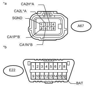
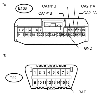
Text in Illustration *A Bus 5 *B Local Bus *a Front view of wire harness connector
(to Millimeter Wave Radar Sensor Assembly)
*b Front view of DLC3 Disconnect the millimeter wave radar sensor assembly connector.
-
Measure the resistance according to the value(s) in the table below.
Bus 5 Terminal No. (Symbol) Wiring Color Switch Condition Specified Condition A67-3 (CA2H) - A67-2 (CA2L) L - B Cable disconnected from negative (-) battery terminal 54 to 69 Ω A67-3 (CA2H) - A67-1 (SGND) L - BR Cable disconnected from negative (-) battery terminal 200 Ω or higher A67-2 (CA2L) - A67-1 (SGND) B - BR Cable disconnected from negative (-) battery terminal 200 Ω or higher A67-3 (CA2H) - E22-16 (BAT) L - L Cable disconnected from negative (-) battery terminal 6 kΩ or higher A67-2 (CA2L) - E22-16 (BAT) B - L Cable disconnected from negative (-) battery terminal 6 kΩ or higher Local Bus Terminal No. (Symbol) Wiring Color Switch Condition Specified Condition A67-5 (CA1P) - A67-6 (CA1N) B - P Cable disconnected from negative (-) battery terminal 108 to 132 Ω A67-5 (CA1P) - A67-1 (SGND) B - BR Cable disconnected from negative (-) battery terminal 200 Ω or higher A67-6 (CA1N) - A67-1 (SGND) P - BR Cable disconnected from negative (-) battery terminal 200 Ω or higher A67-5 (CA1P) - E22-16 (BAT) B - L Cable disconnected from negative (-) battery terminal 6 kΩ or higher A67-6 (CA1N) - E22-16 (BAT) P - L Cable disconnected from negative (-) battery terminal 6 kΩ or higher
-
-
CHECK FORWARD RECOGNITION CAMERA (w/ Pre-crash Safety System)
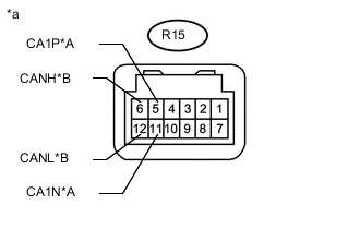
Text in Illustration *A Bus 5 *B Local Bus *a Component without harness connected
(Forward Recognition Camera)
-
Text in Illustration *A Bus 5 *B Local Bus *a Front view of wire harness connector
(to Forward Recognition Camera)
*b Front view of DLC3 Disconnect the forward recognition camera connector.
-
Measure the resistance according to the value(s) in the table below.
Bus 5 Terminal No. (Symbol) Wiring Color Switch Condition Specified Condition R15-5 (CA1P) - R15-11 (CA1N) G - B Cable disconnected from negative (-) battery terminal 54 to 69 Ω R15-5 (CA1P) - R15-10 (GND) G - BR Cable disconnected from negative (-) battery terminal 200 Ω or higher R15-11 (CA1N) - R15-10 (GND) B - BR Cable disconnected from negative (-) battery terminal 200 Ω or higher R15-5 (CA1P) - E22-16 (BAT) G - L Cable disconnected from negative (-) battery terminal 6 kΩ or higher R15-11 (CA1N) - E22-16 (BAT) B - L Cable disconnected from negative (-) battery terminal 6 kΩ or higher Local Bus Terminal No. (Symbol) Wiring Color Switch Condition Specified Condition R15-6 (CANH) - R15-12 (CANL) R - P Cable disconnected from negative (-) battery terminal 108 to 132 Ω R15-6 (CANH) - R15-10 (GND) R - BR Cable disconnected from negative (-) battery terminal 200 Ω or higher R15-12 (CANL) - R15-10 (GND) P - BR Cable disconnected from negative (-) battery terminal 200 Ω or higher R15-6 (CANH) - E22-16 (BAT) R - L Cable disconnected from negative (-) battery terminal 6 kΩ or higher R15-12 (CANL) - E22-16 (BAT) P - L Cable disconnected from negative (-) battery terminal 6 kΩ or higher
-
-
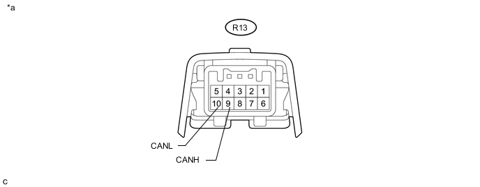
CHECK INNER REAR VIEW MIRROR ASSEMBLY (w/o Pre-crash Safety System)
Text in Illustration *a Component without harness connected
(Inner Rear View Mirror Assembly)
- -
-
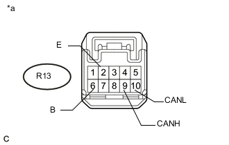
Text in Illustration *a Front view of wire harness connector
(to Inner Rear View Mirror Assembly)
Disconnect the inner rear view mirror assembly connector.
-
Measure the resistance according to the value(s) in the table below.
Terminal No. (Symbol) Wiring Color Switch Condition Specified Condition R13-9 (CANH) - R13-10 (CANL) G - B Cable disconnected from negative (-) battery terminal 54 to 69 Ω R13-9 (CANH) - R13-2 (E) G - W-B Cable disconnected from negative (-) battery terminal 200 Ω or higher R13-10 (CANL) - R13-2 (E) B - W-B Cable disconnected from negative (-) battery terminal 200 Ω or higher R13-9 (CANH) - R13-6 (B) G - G Cable disconnected from negative (-) battery terminal 6 kΩ or higher R13-10 (CANL) - R13-6 (B) B - G Cable disconnected from negative (-) battery terminal 6 kΩ or higher
-
-
CHECK BLIND SPOT MONITOR SENSOR LH (w/ Blind Spot Monitor System)

Text in Illustration *a Component without harness connected
(Blind Spot Monitor Sensor LH)
- -
-
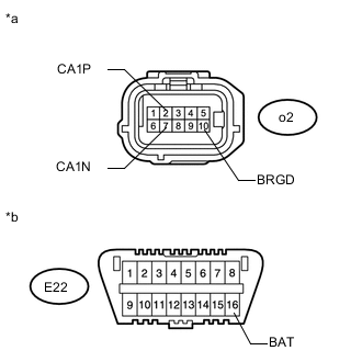
Text in Illustration *a Front view of wire harness connector
(to Blind Spot Monitor Sensor LH)
*b Front view of DLC3 Disconnect the blind spot monitor sensor LH connector.
-
Measure the resistance according to the value(s) in the table below.
Terminal No. (Symbol) Wiring Color Switch Condition Specified Condition o2-2 (CA1P) - o2-7 (CA1N) R - B Cable disconnected from negative (-) battery terminal 54 to 69 Ω o2-2 (CA1P) - o2-10 (BRGD) R - BR Cable disconnected from negative (-) battery terminal 200 Ω or higher o2-7 (CA1N) - o2-10 (BRGD) B - BR Cable disconnected from negative (-) battery terminal 200 Ω or higher o2-2 (CA1P) - E22-16 (BAT) R - L Cable disconnected from negative (-) battery terminal 6 kΩ or higher o2-7 (CA1N) - E22-16 (BAT) B - L Cable disconnected from negative (-) battery terminal 6 kΩ or higher
-
-
CHECK OUTER MIRROR CONTROL ECU ASSEMBLY LH

Text in Illustration *a Component without harness connected
(Outer Mirror Control ECU Assembly LH)
- -
-

Text in Illustration *a Front view of wire harness connector
(to Outer Mirror Control ECU Assembly LH)
Disconnect the outer mirror control ECU assembly LH connector.
-
Measure the resistance according to the value(s) in the table below.
Terminal No. (Symbol) Wiring Color Switch Condition Specified Condition I41-9 (CANP) - I41-8 (CANN) BE - L Cable disconnected from negative (-) battery terminal 54 to 69 Ω I41-9 (CANP) - I41-7 (GND) BE - W-B Cable disconnected from negative (-) battery terminal 200 Ω or higher I41-8 (CANN) - I41-7 (GND) L - W-B Cable disconnected from negative (-) battery terminal 200 Ω or higher I41-9 (CANP) - I41-6 (CPUB) BE - G Cable disconnected from negative (-) battery terminal 6 kΩ or higher I41-8 (CANN) - I41-6 (CPUB) L - G Cable disconnected from negative (-) battery terminal 6 kΩ or higher
-
-
CHECK OUTER MIRROR CONTROL ECU ASSEMBLY RH

Text in Illustration *a Component without harness connected
(Outer Mirror Control ECU Assembly RH)
- -
-
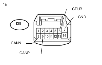
Text in Illustration *a Front view of wire harness connector
(to Outer Mirror Control ECU Assembly RH)
Disconnect the outer mirror control ECU assembly RH connector.
-
Measure the resistance according to the value(s) in the table below.
Terminal No. (Symbol) Wiring Color Switch Condition Specified Condition I38-9 (CANP) - I38-8 (CANN) LG - L Cable disconnected from negative (-) battery terminal 54 to 69 Ω I38-9 (CANP) - I38-7 (GND) LG - W-B Cable disconnected from negative (-) battery terminal 200 Ω or higher I38-8 (CANN) - I38-7 (GND) L - W-B Cable disconnected from negative (-) battery terminal 200 Ω or higher I38-9 (CANP) - I38-6 (CPUB) LG - G Cable disconnected from negative (-) battery terminal 6 kΩ or higher I38-8 (CANN) - I38-6 (CPUB) L - G Cable disconnected from negative (-) battery terminal 6 kΩ or higher
-
-
CHECK MULTIPLEX TILT AND TELESCOPIC ECU

Text in Illustration *a Component without harness connected
(Multiplex Tilt and Telescopic ECU)
- -
-
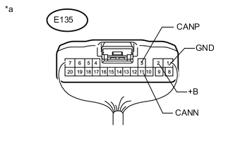
Text in Illustration *a Rear view of wire harness connector
(to Multiplex Tilt and Telescopic ECU)
Disconnect the multiplex tilt and telescopic ECU connector.
-
Measure the resistance according to the value(s) in the table below.
Terminal No. (Symbol) Wiring Color Switch Condition Specified Condition E135-3 (CANP) - E135-11 (CANN) P - L Cable disconnected from negative (-) battery terminal 54 to 69 Ω E135-3 (CANP) - E135-1 (GND) P - W-B Cable disconnected from negative (-) battery terminal 200 Ω or higher E135-11 (CANN) - E135-1 (GND) L - W-B Cable disconnected from negative (-) battery terminal 200 Ω or higher E135-3 (CANP) - E135-2 (+B) P - LA-W Cable disconnected from negative (-) battery terminal 6 kΩ or higher E135-11 (CANN) - E135-2 (+B) L - LA-W Cable disconnected from negative (-) battery terminal 6 kΩ or higher
-
-
CHECK POWER SEAT SWITCH ASSEMBLY

Text in Illustration *a Component without harness connected
(Power Seat Switch Assembly)
- -
-
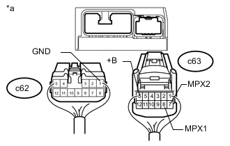
Text in Illustration *a Rear view of wire harness connector
(to Power Seat Switch Assembly)
Disconnect the power seat switch assembly connectors.
-
Measure the resistance according to the value(s) in the table below.
Terminal No. (Symbol) Wiring Color Switch Condition Specified Condition c63-8 (MPX1) - c63-7 (MPX2) V - L Cable disconnected from negative (-) battery terminal 54 to 69 Ω c63-8 (MPX1) - c62-1 (GND) V - W-B Cable disconnected from negative (-) battery terminal 200 Ω or higher c63-7 (MPX2) - c62-1 (GND) L - W-B Cable disconnected from negative (-) battery terminal 200 Ω or higher c63-8 (MPX1) - c63-6 (+B) V - L Cable disconnected from negative (-) battery terminal 6 kΩ or higher c63-7 (MPX2) - c63-6 (+B) L - L Cable disconnected from negative (-) battery terminal 6 kΩ or higher
-
-
CHECK BUS BUFFER ECU (w/ Bus Buffer ECU)
-
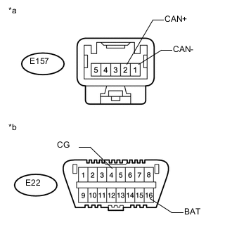
Text in Illustration *a Front view of wire harness connector
(to Bus Buffer ECU)
*b Front view of DLC3 Disconnect the bus buffer ECU connector.
-
Measure the resistance according to the value(s) in the table below.
Terminal No. (Symbol) Wiring Color Switch Condition Specified Condition E157-2 (CAN+) - E157-1 (CAN-) BE - GR Cable disconnected from negative (-) battery terminal 54 to 69 Ω E157-2 (CAN+) - E22-4 (CG) BE - W-B Cable disconnected from negative (-) battery terminal 200 Ω or higher E157-1 (CAN-) - E22-4 (CG) GR - W-B Cable disconnected from negative (-) battery terminal 200 Ω or higher E157-2 (CAN+) - E22-16 (BAT) BE - L Cable disconnected from negative (-) battery terminal 6 kΩ or higher E157-2 (CAN+) - E22-16 (BAT) GR - L Cable disconnected from negative (-) battery terminal 6 kΩ or higher
-
-
CHECK HEADLIGHT ECU SUB-ASSEMBLY LH
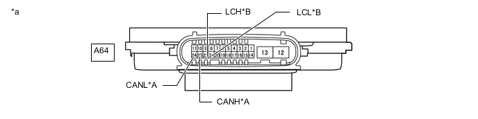
Text in Illustration *A Bus 2 *B Local Bus *a Component without harness connected
(Headlight ECU Sub-assembly LH)
- -
-
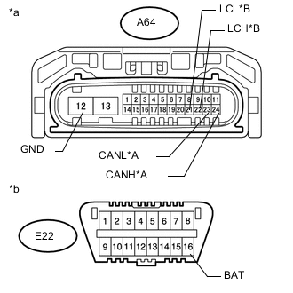
Text in Illustration *A Bus 2 *B Local Bus *a Front view of wire harness connector
(to Headlight ECU Sub-assembly LH)
*b Front view of DLC3 Disconnect the headlight ECU sub-assembly LH connector.
-
Measure the resistance according to the value(s) in the table below.
Bus 2 Terminal No. (Symbol) Wiring Color Switch Condition Specified Condition A64-24 (CANH) - A64-23 (CANL) LG - B Cable disconnected from negative (-) battery terminal 54 to 69 Ω A64-24 (CANH) - A64-12 (GND) LG - W-B Cable disconnected from negative (-) battery terminal 200 Ω or higher A64-23 (CANL) - A64-12 (GND) B - W-B Cable disconnected from negative (-) battery terminal 200 Ω or higher A64-24 (CANH) - E22-16 (BAT) LG - L Cable disconnected from negative (-) battery terminal 6 kΩ or higher A64-23 (CANL) - E22-16 (BAT) B - L Cable disconnected from negative (-) battery terminal 6 kΩ or higher Local Bus Terminal No. (Symbol) Wiring Color Switch Condition Specified Condition A64-22 (LCH) - A64-21 (LCL) L - P Cable disconnected from negative (-) battery terminal 54 to 69 Ω A64-22 (LCH) - A64-12 (GND) L - W-B Cable disconnected from negative (-) battery terminal 200 Ω or higher A64-21 (LCL) - A64-12 (GND) P - W-B Cable disconnected from negative (-) battery terminal 200 Ω or higher A64-22 (LCH) - E22-16 (BAT) L - L Cable disconnected from negative (-) battery terminal 6 kΩ or higher A64-21 (LCL) - E22-16 (BAT) P - L Cable disconnected from negative (-) battery terminal 6 kΩ or higher
-
-
CHECK HEADLIGHT ECU SUB-ASSEMBLY RH (w/ Pre-crash Safety System)
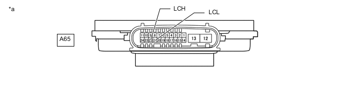
Text in Illustration *a Component without harness connected
(Headlight ECU Sub-assembly RH)
- -
-
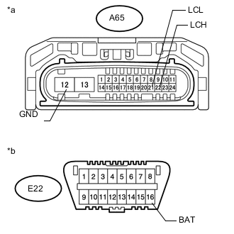
Text in Illustration *a Front view of wire harness connector
(to Headlight ECU Sub-assembly RH)
*b Front view of DLC3 Disconnect the headlight ECU sub-assembly RH connector.
-
Measure the resistance according to the value(s) in the table below.
Terminal No. (Symbol) Wiring Color Switch Condition Specified Condition A65-22 (LCH) - A65-21 (LCL) BE - P Cable disconnected from negative (-) battery terminal 54 to 69 Ω A65-22 (LCH) - A65-12 (GND) BE - W-B Cable disconnected from negative (-) battery terminal 200 Ω or higher A65-21 (LCL) - A65-12 (GND) P - W-B Cable disconnected from negative (-) battery terminal 200 Ω or higher A65-22 (LCH) - E22-16 (BAT) BE - L Cable disconnected from negative (-) battery terminal 6 kΩ or higher A65-21 (LCL) - E22-16 (BAT) P - L Cable disconnected from negative (-) battery terminal 6 kΩ or higher
-
-
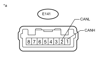
CHECK POWER STEERING ECU ASSEMBLY
Text in Illustration *a Component without harness connected
(Power Steering ECU Assembly)
-
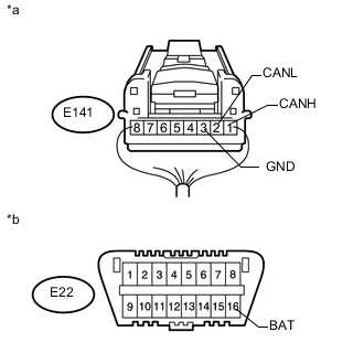
Text in Illustration *a Front view of wire harness connector
(to Power Steering ECU Assembly)
*b Front view of DLC3 Disconnect the power steering ECU assembly connector.
-
Measure the resistance according to the value(s) in the table below.
Terminal No. (Symbol) Wiring Color Switch Condition Specified Condition E141-1 (CANH) - E141-2 (CANL) LG - W Cable disconnected from negative (-) battery terminal 54 to 69 Ω E141-1 (CANH) - E141-3 (GND) LG - W-B Cable disconnected from negative (-) battery terminal 200 Ω or higher E141-2 (CANL) - E141-3 (GND) W - W-B Cable disconnected from negative (-) battery terminal 200 Ω or higher E141-1 (CANH) - E22-16 (BAT) LG - L Cable disconnected from negative (-) battery terminal 6 kΩ or higher E141-2 (CANL) - E22-16 (BAT) W - L Cable disconnected from negative (-) battery terminal 6 kΩ or higher
-
-
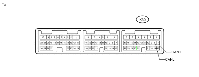
CHECK SUSPENSION CONTROL ECU
Text in Illustration *a Component without harness connected
(Suspension Control ECU)
- -
-
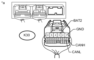
Text in Illustration *a Rear view of wire harness connector
(to Suspension Control ECU)
Disconnect the suspension control ECU connector.
-
Measure the resistance according to the value(s) in the table below.
Terminal No. (Symbol) Wiring Color Switch Condition Specified Condition K30-7 (CANH) - K30-8 (CANL) L - B Cable disconnected from negative (-) battery terminal 54 to 69 Ω K30-7 (CANH) - K30-1 (GND) L - W-B Cable disconnected from negative (-) battery terminal 200 Ω or higher K30-8 (CANL) - K30-1 (GND) B - W-B Cable disconnected from negative (-) battery terminal 200 Ω or higher K30-7 (CANH) - K30-3 (BAT2) L - R Cable disconnected from negative (-) battery terminal 6 kΩ or higher K30-8 (CANL) - K30-3 (BAT2) B - R Cable disconnected from negative (-) battery terminal 6 kΩ or higher
-
-
CHECK POWER BACK DOOR UNIT ASSEMBLY (POWER BACK DOOR ECU)

Text in Illustration *a Component without harness connected
(Power Back Door Unit Assembly [Power Back Door ECU])
- -
-
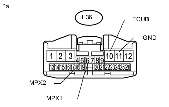
Text in Illustration *a Front view of wire harness connector
(to Power Back Door Unit Assembly [Power Back Door ECU])
Disconnect the power back door unit assembly (power back door ECU) connector.
-
Measure the resistance according to the value(s) in the table below.
Terminal No. (Symbol) Wiring Color Switch Condition Specified Condition L36-6 (MPX1) - L36-5 (MPX2) V - L Cable disconnected from negative (-) battery terminal 54 to 69 Ω L36-6 (MPX1) - L36-11 (GND) V - W-B Cable disconnected from negative (-) battery terminal 200 Ω or higher L36-5 (MPX2) - L36-11 (GND) L - W-B Cable disconnected from negative (-) battery terminal 200 Ω or higher L36-6 (MPX1) - L36-10 (ECUB) V - R Cable disconnected from negative (-) battery terminal 6 kΩ or higher L36-5 (MPX2) - L36-10 (ECUB) L - R Cable disconnected from negative (-) battery terminal 6 kΩ or higher
-
-
CHECK NO. 2 MAIN BODY ECU
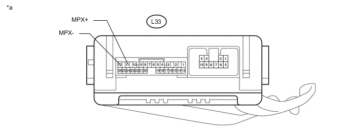
Text in Illustration *a Component without harness connected
(No. 2 Main Body ECU)
- -
-
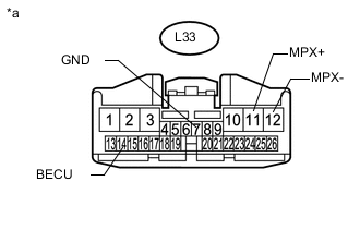
Text in Illustration *a Front view of wire harness connector
(to No. 2 Main Body ECU)
Disconnect the No. 2 main body ECU connector.
-
Measure the resistance according to the value(s) in the table below.
Terminal No. (Symbol) Wiring Color Switch Condition Specified Condition L33-11 (MPX+) - L33-12 (MPX-) LG - L Cable disconnected from negative (-) battery terminal 54 to 69 Ω L33-11 (MPX+) - L33-7 (GND) LG - W-B Cable disconnected from negative (-) battery terminal 200 Ω or higher L33-12 (MPX-) - L33-7 (GND) L - W-B Cable disconnected from negative (-) battery terminal 200 Ω or higher L33-11 (MPX+) - L33-14 (ECUB) LG - R Cable disconnected from negative (-) battery terminal 6 kΩ or higher L33-12 (MPX-) - L33-14 (ECUB) L - R Cable disconnected from negative (-) battery terminal 6 kΩ or higher
-
-
CHECK METER MIRROR SUB-ASSEMBLY (w/ Headup Display System)

Text in Illustration *a Component without harness connected
(Meter Mirror Sub-assembly)
- -
-
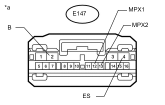
Text in Illustration *a Front view of wire harness connector
(to Meter Mirror Sub-assembly)
Disconnect the meter mirror sub-assembly connector.
-
Measure the resistance according to the value(s) in the table below.
Terminal No. (Symbol) Wiring Color Switch Condition Specified Condition E147-12 (MPX1) - E147-13 (MPX2) B - W Cable disconnected from negative (-) battery terminal 54 to 69 Ω E147-12 (MPX1) - E147-4 (ES) B - W-B Cable disconnected from negative (-) battery terminal 200 Ω or higher E147-13 (MPX2) - E147-4 (ES) W - W-B Cable disconnected from negative (-) battery terminal 200 Ω or higher E147-12 (MPX1) - E147-2 (B) B - G Cable disconnected from negative (-) battery terminal 6 kΩ or higher E147-13 (MPX2) - E147-2 (B) W - G Cable disconnected from negative (-) battery terminal 6 kΩ or higher
-
-
CHECK PARKING BRAKE ECU ASSEMBLY

Text in Illustration *a Component without harness connected
(Parking Brake ECU Assembly)
- -
-
Disconnect the parking brake ECU assembly connectors.
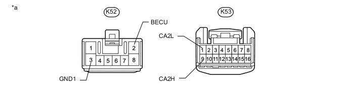
Text in Illustration *a Front view of wire harness connector
(to Parking Brake ECU Assembly)
- - -
Measure the resistance according to the value(s) in the table below.
Terminal No. (Symbol) Wiring Color Switch Condition Specified Condition K53-9 (CA2H) - K53-1 (CA2L) LG - B Cable disconnected from negative (-) battery terminal 54 to 69 Ω K53-9 (CA2H) - K52-3 (GND1) LG - W-B Cable disconnected from negative (-) battery terminal 200 Ω or higher K53-1 (CA2L) - K52-3 (GND1) B - W-B Cable disconnected from negative (-) battery terminal 200 Ω or higher K53-9 (CA2H) - K52-2 (BECU) LG - L Cable disconnected from negative (-) battery terminal 6 kΩ or higher K53-1 (CA2L) - K52-2 (BECU) B - L Cable disconnected from negative (-) battery terminal 6 kΩ or higher
-