CAN COMMUNICATION SYSTEM(for LHD) SYSTEM DIAGRAM
-
SYSTEM DIAGRAM
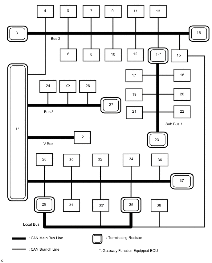
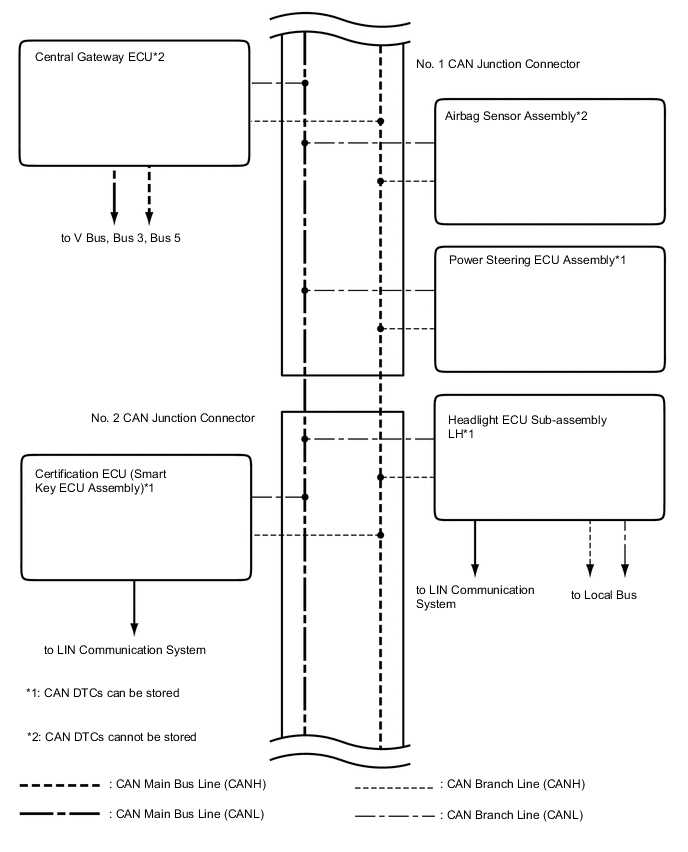
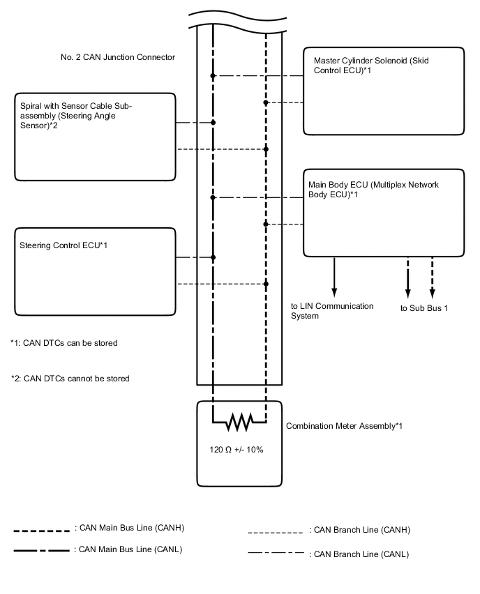
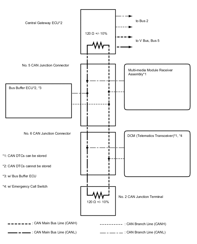
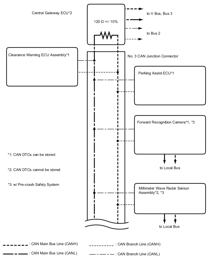
No. ECU/Sensor name 1 Central Gateway ECU 2 DLC3 3 ECM 4 4WD Control ECU 5 Power Steering ECU Assembly 6 Tire Pressure Warning ECU*1 7 Airbag Sensor Assembly 8 Air Conditioning Amplifier Assembly 9 Meter Mirror Sub-assembly*7 10 Master Cylinder Solenoid (Skid Control ECU) 11 Steering Control ECU 12 Certification ECU (Smart Key ECU Assembly) 13 Spiral with Sensor Cable Sub-assembly (Steering Angle Sensor) 14 Main Body ECU (Multiplex Network Body ECU) 15 Headlight ECU Sub-assembly LH 16 Combination Meter Assembly 17 Outer Mirror Control ECU Assembly RH 18 Outer Mirror Control ECU Assembly LH 19 Power Seat Switch Assembly 20 Multiplex Tilt and Telescopic ECU 21 Power Back Door Unit Assembly (Power Back Door ECU) 22 No. 2 Main Body ECU 23 No. 3 CAN Junction Terminal 24 Multi-media Module Receiver Assembly 25 Bus Buffer ECU*2 26 DCM (Telematics Transceiver)*3 27 No. 2 CAN Junction Terminal 28 Parking Assist ECU 29 Forward Recognition Camera*4 30 Parking Brake ECU Assembly 31 Suspension Control ECU 32 Clearance Warning ECU Assembly 33 Driving Support ECU Assembly*4 34 Inner Rear View Mirror Assembly*5 35 Millimeter Wave Radar Sensor Assembly*4 36 Blind Spot Monitor Sensor LH*6 37 No. 1 CAN Junction Terminal 38 Headlight ECU Sub-assembly RH
-
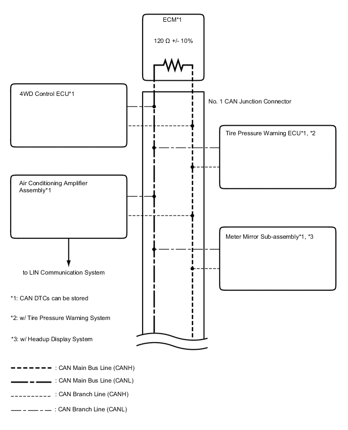
*1: w/ Tire Pressure Warning System
-
*2: w/ Bus Buffer ECU
-
*3: w/ Emergency Call Switch
-
*4: w/ Pre-crash Safety System
-
*5: w/o Pre-crash Safety System
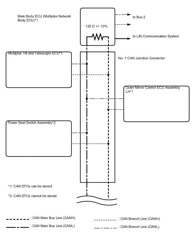
-
*6: w/ Blind Spot Monitor System
-
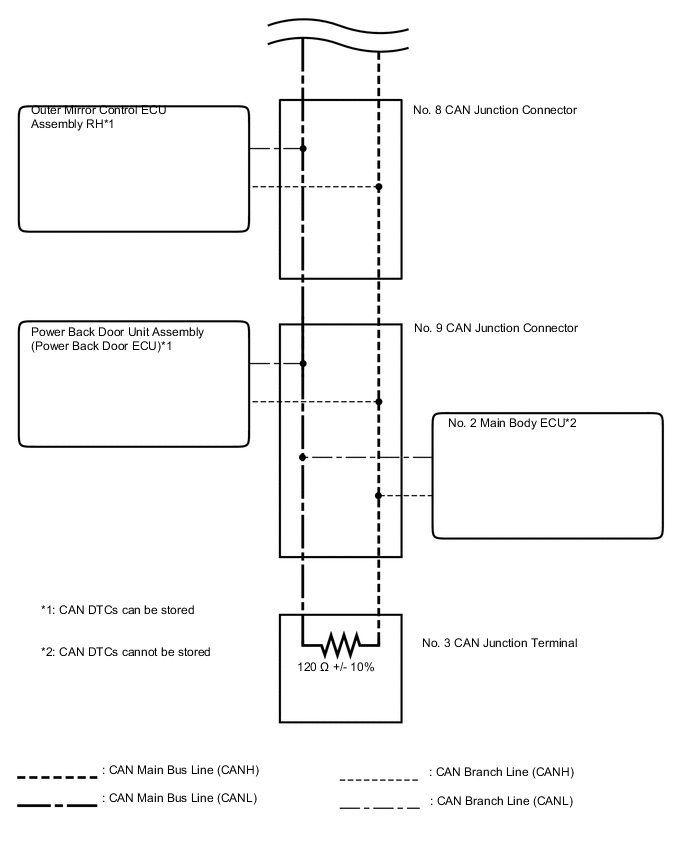
*7: w/ Headup Display System
Tech Tips
-
The main body ECU (multiplex network body ECU) functions as a gateway between the bus 2 and sub bus 1.
-
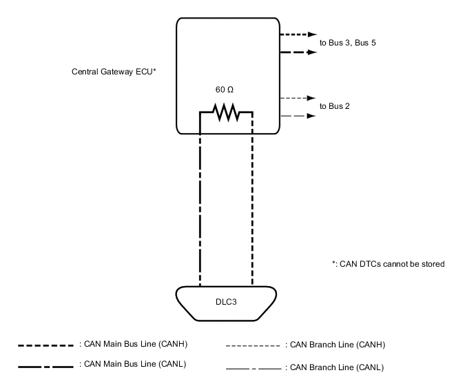
The central gateway ECU functions as a gateway between the V bus, bus 2, bus 3 and bus 5.
-
The driving support ECU assembly functions as a gateway between the bus 5 and local bus.
-
Refer to the following bus wiring diagrams for details.
-
-
V BUS
-
BUS 2
-
BUS 3
-
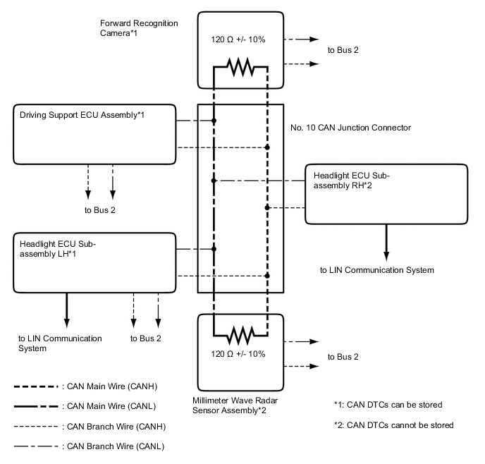
BUS 5
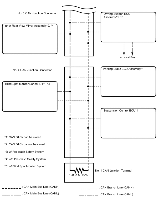
-
SUB BUS 1
-
LOCAL BUS (w/ Pre-crash Safety System)