GENERATOR(for 180 A Type) REMOVAL

PROCEDURE
-
PRECAUTION
Note
After turning the engine switch off, waiting time may be required before disconnecting the cable from the battery terminal. Therefore, make sure to read the disconnecting the cable from the battery terminal notice before proceeding with work Click here.
-
DISCONNECT CABLE FROM NEGATIVE BATTERY TERMINAL
Note
When disconnecting the cable, some systems need to be initialized after the cable is reconnected Click here.
-
REMOVE FRONT FENDER SPLASH SHIELD SUB-ASSEMBLY LH
-
REMOVE FRONT FENDER SPLASH SHIELD SUB-ASSEMBLY RH
-
REMOVE NO. 1 ENGINE UNDER COVER SUB-ASSEMBLY
-
DRAIN ENGINE COOLANT
-
REMOVE FRONT FENDER APRON SEAL FRONT RH
-
REMOVE FRONT FENDER APRON SEAL REAR RH
-
REMOVE V-RIBBED BELT (w/ Viscous Heater)
-
REMOVE NO. 1 IDLER PULLEY (w/ Viscous Heater)
-
REMOVE NO. 3 IDLER PULLEY (w/ Viscous Heater)
-
REMOVE V-RIBBED BELT
-
REMOVE INTERCOOLER ASSEMBLY
-
DISCONNECT WATER HOSE SUB-ASSEMBLY (w/ Viscous Heater)
-
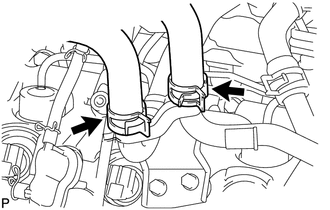
Slide the 2 clamps and disconnect the 2 water hoses.
-
-
REMOVE NO. 2 ENGINE OIL LEVEL DIPSTICK GUIDE
-
REMOVE AIR CLEANER CAP SUB-ASSEMBLY
-
REMOVE NO. 1 AIR CLEANER HOSE
-
REMOVE INTAKE AIR CONNECTOR
-
REMOVE NO. 1 AIR HOSE
-
REMOVE NO. 3 AIR TUBE
-
REMOVE HEATER WATER PIPE SUB-ASSEMBLY (w/ Viscous Heater)
-
REMOVE NO. 1 AIR CLEANER PIPE SUB-ASSEMBLY
-
REMOVE NO. 1 AIR TUBE ASSEMBLY
-
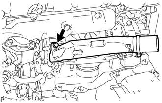
Remove the bolt and No. 1 air tube assembly.
-
Remove the O-ring.
-
-
REMOVE GENERATOR ASSEMBLY
-
Disconnect the 4 connectors.
-
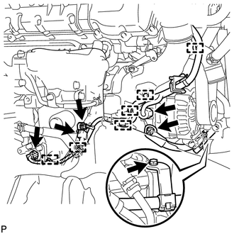
Disconnect the 6 wire harness clamps.
-
Remove the terminal cap.
-
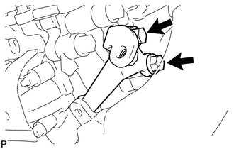
Remove the nut and disconnect the generator wire.
-
Remove the bolt and disconnect the wire harness bracket from the belt tensioner.
-
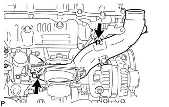
Loosen the clamp and remove the bolt.
-
Remove the 2 bolts and No. 1 intake air connector bracket.
-
Remove the No. 1 intake air connector pipe from the No. 1 inlet compressor elbow.
-
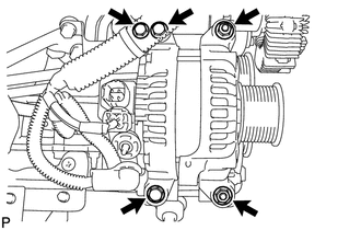
Remove the 3 bolts and 2 nuts.
-
Using an E7 "TORX" socket wrench, remove the 2 stud bolts and generator assembly.
-