GENERATOR(for 150 A Type) INSPECTION

PROCEDURE
-
INSPECT GENERATOR ROTOR ASSEMBLY
-
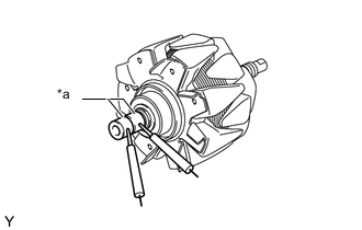
Text in Illustration *a Slip Ring Check the the resistance.
-
Measure the resistance according to the value(s) in the table below.
Standard Resistance Tester Connection Condition Specified Condition Slip ring - Slip ring 20°C (68°F) 1.5 to 1.9 Ω If the result is not as specified, replace the generator rotor assembly.
-
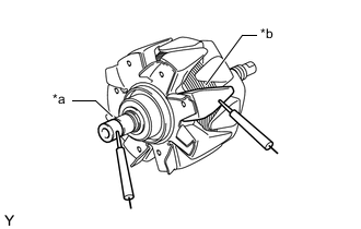
Text in Illustration *a Slip Ring *b Rotor Core Measure the resistance according to the value(s) in the table below.
Standard Resistance Tester Connection Condition Specified Condition Slip ring - Rotor core Always 10 MΩ or higher If the result is not as specified, replace the generator rotor assemby
-
-
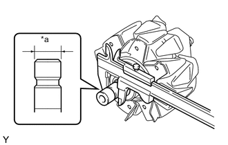
Text in Illustration *a Diameter Using a vernier caliper, measure each slip ring diameter.
Standard diameter 14.2 to 14.8 mm (0.559 to 0.583 in.) Minimum diameter 14.0 mm (0.551 in.) If the diameter is less than the minimum, replace the rotor assembly.
-
-
INSPECT GENERATOR ROTOR BEARING
-
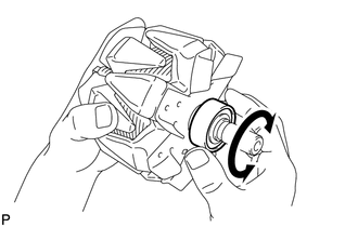
Check that the generator rotor bearing is not rough or worn.
If necessary, replace the generator rotorassembly.
-
-
INSPECT GENERATOR BRUSH HOLDER ASSEMBLY
-
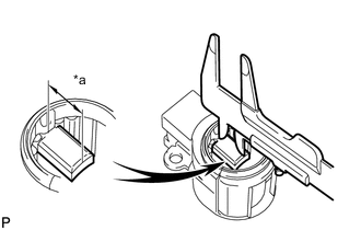
Text in Illustration *a Length Using a vernier caliper, measure the exposed brush length.
Standard exposed length 9.5 to 11.5 mm (0.374 to 0.453 in.) Minimum exposed length 4.5 mm (0.177 in.) If the length is less than the minimum, replace the generator brush holder assembly.
-