GENERATOR(for 180 A Type) DISASSEMBLY

PROCEDURE
-
REMOVE GENERATOR PULLEY
-
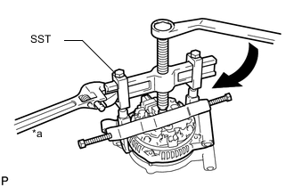
Mount the generator assembly in a vise between aluminum plates.
-
Install SST 1-A and SST 1-B to the generator rotor shaft.
- SST
- 09820-63011 ( 09820-06010, 09820-06021 )
Tech Tips
SST 1-A and B 09820-06010 SST 2 09820-06021 -
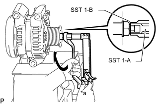
Text in Illustration *a Hold 
Turn Hold SST 1-A with a torque wrench and turn SST 1-B clockwise with the specified torque.
- Torque:
- 39 N*m { 398 kgf*cm, 29 ft.*lbf }
Note
Check that SST is secured on the rotor shaft.
-
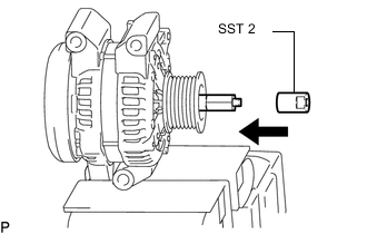
Insert SST 2 and attach it to the pulley nut.
Text in Illustration Insert -
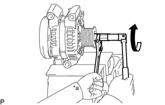
Text in Illustration *a Hold Turn To loosen the pulley nut, turn SST 1-A in the direction shown in the illustration.
Note
To prevent damage to the rotor shaft, do not loosen the pulley nut more than one-half turn.
-
Remove SST 2.
-
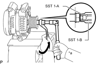
Text in Illustration *a Hold Turn Turn SST 1-B in the direction shown in the illustration, and then remove SST 1-A and SST 1-B.
-
Remove the pulley nut and generator pulley.
-
-
REMOVE GENERATOR REAR END COVER
-
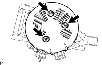
Remove the 3 nuts and generator rear end cover.
-
-
REMOVE TERMINAL INSULATOR
-
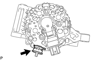
Remove the terminal insulator from generator coil assembly.
-
-
REMOVE GENERATOR BRUSH HOLDER ASSEMBLY
-
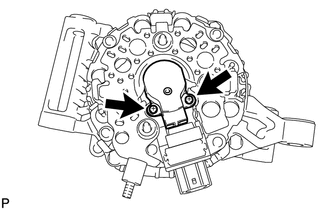
Remove the 2 screws and generator brush holder assembly.
-
-
REMOVE GENERATOR COIL ASSEMBLY
-
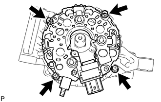
Remove the 4 bolts.
-
Text in Illustration *a Hold Turn Using SST, remove the generator coil assembly.
- SST
- 09950-40011 ( 09951-04020, 09952-04010, 09953-04020, 09954-04010, 09955-04071, 09957-04010, 09958-04011 )
-
-
REMOVE GENERATOR ROTOR ASSEMBLY
-
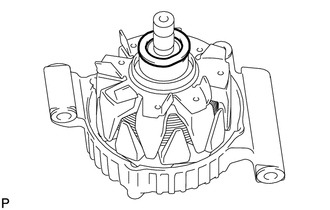
Remove the generator washer and generator rotor assembly.
-
-
INSPECT GENERATOR DRIVE END FRAME BEARING
-
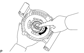
Check that the generator drive end frame bearing is not rough or worn.
If necessary, replace the generator drive end frame bearing.
-
-
REPLACE GENERATOR DRIVE END FRAME BEARING
-
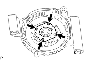
Remove the 4 screws and retainer plate.
-
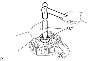
Using SST and a hammer, tap out the generator drive end frame bearing.
- SST
- 09950-60010 ( 09951-00250 )
- 09950-70010 ( 09951-07100 )
-