ULTRASONIC SENSOR(for Front) REMOVAL
PROCEDURE
-
REMOVE FRONT BUMPER COVER
-
REMOVE NO. 1 ULTRASONIC SENSOR
Tech Tips
The illustration shows the No. 1 ultrasonic sensor for the LH. The horizontal orientation of the No. 1 ultrasonic sensor for the RH is opposite that of the image shown in the illustration.
-
Disconnect the connector.
-
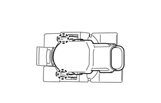
Detach the 2 claws and remove the No. 1 ultrasonic sensor.
-
-
REMOVE NO. 1 ULTRASONIC SENSOR RETAINER
Tech Tips
-
When removing the No. 1 ultrasonic sensor retainer, heat the front bumper cover and No. 1 ultrasonic sensor retainer using a heat light.
-
The illustration shows the No. 1 ultrasonic sensor retainer for the LH. The horizontal orientation of the No. 1 ultrasonic sensor retainer for the RH is opposite that of the image shown in the illustration.
Standard Item Temperature Front Bumper Cover 40 to 60°C (104 to 140°F) No. 1 Ultrasonic Sensor Retainer 40 to 60°C (104 to 140°F) Note
Do not heat the front bumper cover or No. 1 ultrasonic sensor retainer excessively.
-
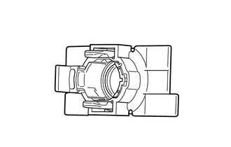
Remove the No. 1 ultrasonic sensor retainer.
-
-
REMOVE FRONT BUMPER LOWER COVER
-
REMOVE RADIATOR GRILLE SUB-ASSEMBLY
-
REMOVE NO. 4 ENGINE ROOM WIRE
-
REMOVE FRONT BUMPER MOULDING COVER
-
REMOVE NO. 3 ULTRASONIC SENSOR
Tech Tips
The illustration shows the No. 3 ultrasonic sensor for the LH. The horizontal orientation of the No. 3 ultrasonic sensor for the RH is opposite that of the image shown in the illustration.
-
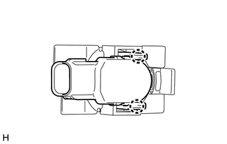
Detach the 2 claws and remove the No. 3 ultrasonic sensor.
-
-
REMOVE NO. 3 ULTRASONIC SENSOR RETAINER
Tech Tips
-
When removing the No. 3 ultrasonic sensor retainer, heat the front bumper cover and No. 3 ultrasonic sensor retainer using a heat light.
-
The illustration shows the No. 3 ultrasonic sensor retainer for the LH. The horizontal orientation of the No. 3 ultrasonic sensor retainer for the RH is opposite that of the image shown in the illustration.
Standard Item Temperature Front Bumper Cover 40 to 60°C (104 to 140°F) No. 3 Ultrasonic Sensor Retainer 40 to 60°C (104 to 140°F) Note
Do not heat the front bumper cover or No. 3 ultrasonic sensor retainer excessively.
-
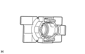
Remove the No. 3 ultrasonic sensor retainer.
-