MULTI-TERRAIN MONITOR SYSTEM, Diagnostic DTC:C1682
| DTC Code | DTC Name |
|---|---|
| C1682 | Front Camera Current Malfunction |
DESCRIPTION
DTC C1682 is stored if the parking assist ECU judges as a result of its self check that there is a problem with the current supplied from the front television camera assembly connected to the parking assist ECU.
| DTC Code | DTC Detection Condition | Trouble Area |
|---|---|---|
| C1682 | An open or short in the front television camera signal circuit |
|
WIRING DIAGRAM
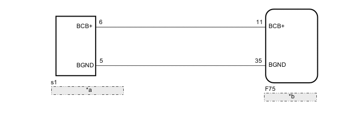
| *a | Front Television Camera Assembly |
| *b | Parking Assist ECU |
CAUTION / NOTICE / HINT
Note
-
When "!" mark is displayed on the multi-display after the cable is disconnected from the negative (-) battery terminal, correct the steering angle neutral point Click here.
-
Depending on the parts that are replaced or operations that are performed during vehicle inspection or maintenance, calibration of other systems as well as multi-terrain monitor system may be needed Click here.
PROCEDURE
-
CHECK HARNESS AND CONNECTOR (PARKING ASSIST ECU - FRONT TELEVISION CAMERA ASSEMBLY)
-
Disconnect the F75 parking assist ECU connector.
-
Disconnect the s1 front television camera assembly connector.
-
Measure the resistance according to the value(s) in the table below.
Standard Resistance Tester Connection Condition Specified Condition F75-11 (BCB+) - s1-6 (BCB+) Always Below 1 Ω F75-35 (BGND) - s1-5 (BGND) Always Below 1 Ω F75-11 (BCB+) or s1-6 (BCB+) - Body ground Always 10 kΩ or higher F75-35 (BGND) or s1-5 (BGND) - Body ground Always 10 kΩ or higher
NG 
REPAIR OR REPLACE HARNESS OR CONNECTOR
OK 
-
-
CHECK PARKING ASSIST ECU (BCB+, BGND)
-
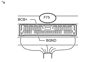
Text in Illustration *a Component with harness connected
(Parking Assist ECU)
Measure the resistance according to the value(s) in the table below.
Standard Resistance Tester Connection Condition Specified Condition F75-35 (BGND) - Body ground Always Below 1 Ω -
Measure the voltage according to the value(s) in the table below.
Standard Voltage Tester Connection Switch Condition Specified Condition F75-11 (BCB+) - F75-35 (BGND) Engine switch on (IG) 5.5 to 7.05 V
OK
REPLACE FRONT TELEVISION CAMERA ASSEMBLY Click here
NG
REPLACE PARKING ASSIST ECU Click here
-