MULTI-TERRAIN MONITOR SYSTEM, Diagnostic DTC:U0265, U0266, U0267, U0268
| DTC Code | DTC Name |
|---|---|
| U0265 | Lost Communication with Image Processing Sensor A |
| U0266 | Lost Communication with Image Processing Sensor B |
| U0267 | Lost Communication with Image Processing Sensor C |
| U0268 | Lost Communication with Image Processing Sensor D |
DESCRIPTION
| DTC Code | DTC Detection Condition | Trouble Area |
|---|---|---|
| U0265 | Lost Communication with rear television camera assembly |
|
| U0266 | Lost Communication with side television camera assembly LH |
|
| U0267 | Lost Communication with front television camera assembly |
|
| U0268 | Lost Communication with side television camera assembly RH |
|
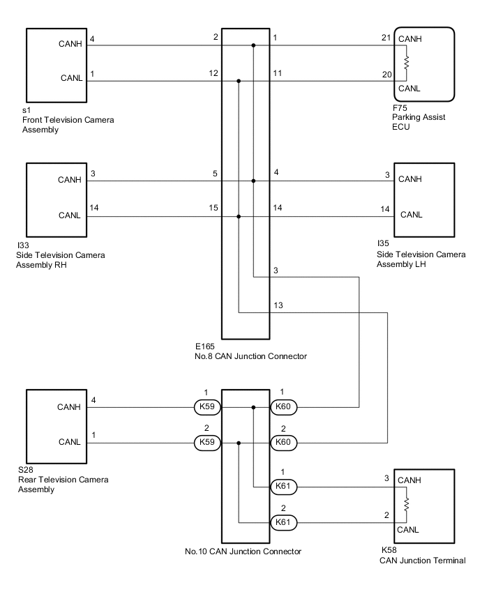
WIRING DIAGRAM
CAUTION / NOTICE / HINT
Note
-
Before measuring the resistance of the CAN bus, turn the engine switch off and leave the vehicle for 1 minute or more without operating the key, switches or opening or closing the doors. After that, disconnect the cable from the negative (-) battery terminal and leave the vehicle for 1 minute or more before measuring the resistance.
-
After turning the engine switch off, waiting time may be required before disconnecting the cable from the battery terminal. Therefore, make sure to read the disconnecting the cable from the battery terminal notice before proceeding with work Click here.
Tech Tips
-
Operating the engine switch, any other switches or a door triggers related ECU and sensor communication on the CAN. This communication will cause the resistance value to change.
-
Even after DTCs are cleared, if a DTC is stored again after driving the vehicle for a while, the malfunction may be occurring due to vibration of the vehicle. In such a case, wiggling the ECUs or wire harness while performing the inspection below may help determine the cause of the malfunction.
PROCEDURE
-
CHECK FOR DTC
-
Clear the DTCs Click here.
-
Check for DTCs Click here.
Result Result Proceed to DTC U0265, U0266, U0267 and U0268 are not output A DTC U0265, U0266, U0267 and U0268 are output B DTC U0265, U0266, U0267 or U0268 are output C
A 
USE SIMULATION METHOD TO CHECK Click here
C 
CHECK FOR DTC Click here
B 
-
-
CHECK CAN BUS WIRE (PARKING ASSIST ECU)
-
Disconnect the parking assist ECU connector.
-
Measure the resistance according to the value(s) in the table below.
Standard Resistance Tester Connection Condition Specified Condition F75-21 (CANH) - F75-20 (CANL) Cable disconnected from negative (-) battery terminal 108 to 132 Ω F75-21 (CANH) - E22-4 (CG) Cable disconnected from negative (-) battery terminal 200 Ω or higher F75-20 (CANL) - E22-4 (CG) Cable disconnected from negative (-) battery terminal 200 Ω or higher F75-21 (CANH) - E22-16 (BAT) Cable disconnected from negative (-) battery terminal 6 kΩ or higher F75-20 (CANL) - E22-16 (BAT) Cable disconnected from negative (-) battery terminal 6 kΩ or higher
OK
REPLACE PARKING ASSIST ECU Click here
NG
-
-
CONNECT CONNECTOR
-
Reconnect the F75 parking assist ECU connector.
NEXT
-
-
CHECK CAN BUS WIRE (CAN JUNCTION TERMINAL)
-
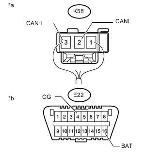
Text in Illustration *a Rear view of harness connector
(to CAN Junction Terminal)
*b Front view of DLC3 Disconnect the CAN junction terminal connector.
-
Measure the resistance according to the value(s) in the table below.
Standard Resistance Tester Connection Condition Specified Condition K58-3 (CANH) - K58-2 (CANL) Cable disconnected from negative (-) battery terminal 108 to 132 Ω K58-3 (CANH) - E22-4 (CG) Cable disconnected from negative (-) battery terminal 200 Ω or higher K58-2 (CANL) - E22-4 (CG) Cable disconnected from negative (-) battery terminal 200 Ω or higher K58-3 (CANH) - E22-16 (BAT) Cable disconnected from negative (-) battery terminal 6 kΩ or higher K58-2 (CANL) - E22-16 (BAT) Cable disconnected from negative (-) battery terminal 6 kΩ or higher
OK
REPLACE CAN JUNCTION TERMINAL
NG
-
-
CONNECT CONNECTOR
-
Reconnect the K58 CAN junction terminal connector.
NEXT
-
-
CHECK CAN BUS WIRE (NO. 8 CAN JUNCTION CONNECTOR)
-
Disconnect the No. 8 CAN junction connector.
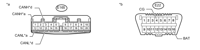
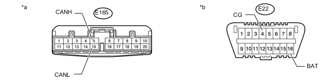
Text in Illustration *a Front view of wire harness connector
(to No. 8 CAN Junction Connector)
*b Front view of DLC3 *c Parking Assist ECU *d No. 10 CAN Junction Connector -
Measure the resistance according to the value(s) in the table below.
Standard Resistance Tester Connection Condition Specified Condition Connect to E165-1 (CANH) - E165-11 (CANL) Cable disconnected from negative (-) battery terminal 108 to 132 Ω Parking Assist ECU E165-1 (CANH) - E22-4 (CG) Cable disconnected from negative (-) battery terminal 200 Ω or higher E165-11 (CANL) - E22-4 (CG) Cable disconnected from negative (-) battery terminal 200 Ω or higher E165-1 (CANH) - E22-16 (BAT) Cable disconnected from negative (-) battery terminal 6 kΩ or higher E165-11 (CANL) - E22-16 (BAT) Cable disconnected from negative (-) battery terminal 6 kΩ or higher E165-3 (CANH) - E165-13 (CANL) Cable disconnected from negative (-) battery terminal 108 to 132 Ω No. 10 CAN Junction Connector E165-3 (CANH) - E22-4 (CG) Cable disconnected from negative (-) battery terminal 200 Ω or higher E165-13 (CANL) - E22-4 (CG) Cable disconnected from negative (-) battery terminal 200 Ω or higher E165-3 (CANH) - E22-16 (BAT) Cable disconnected from negative (-) battery terminal 6 kΩ or higher E165-13 (CANL) - E22-16 (BAT) Cable disconnected from negative (-) battery terminal 6 kΩ or higher Result Result Proceed to OK A NG (to parking assist ECU CAN main wire) B NG (to No. 10 CAN junction connector CAN main wire) C
A
REPLACE NO. 8 CAN JUNCTION CONNECTOR
B
REPAIR OR REPLACE CAN BUS MAIN WIRE OR CONNECTOR (NO. 8 CAN JUNCTION CONNECTOR - PARKING ASSIST ECU)
C
-
-
CONNECT CONNECTOR
-
Reconnect the E165 No. 8 CAN junction connector.
NEXT
-
-
CHECK CAN BUS WIRE (NO. 10 CAN JUNCTION CONNECTOR)
Tech Tips
Connectors that connect to the CAN junction connector can be distinguished by color of their CAN bus lines. When the connectors have been disconnected from the CAN junction connector, reconnecting the connectors to non-original positions on the CAN junction connector does not affect system performance. However, it is preferred to reconnect the connectors to their original positions to avoid negative effects on the wiring such as tension on the wiring harnesses, and to make future maintenance easier.
-
Disconnect the No. 10 CAN junction connector.
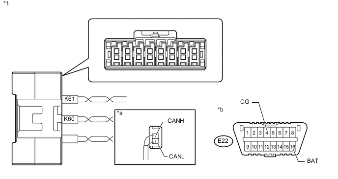
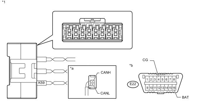
Text in Illustration *1 No. 10 CAN Junction Connector - - *a Rear view of wire harness connector
(to No. 10 CAN Junction Connector)
*b Front view of DLC3 -
Measure the resistance according to the value(s) in the table below.
Standard Resistance Tester Connection Condition Specified Condition Connect to K60-1 (CANH) - K60-2 (CANL) Cable disconnected from negative (-) battery terminal 108 to 132 Ω No. 8 Junction Connector K60-1 (CANH) - E22-4 (CG) Cable disconnected from negative (-) battery terminal 200 Ω or higher K60-2 (CANL) - E22-4 (CG) Cable disconnected from negative (-) battery terminal 200 Ω or higher K60-1 (CANH) - E22-16 (BAT) Cable disconnected from negative (-) battery terminal 6 kΩ or higher K60-2 (CANL) - E22-16 (BAT) Cable disconnected from negative (-) battery terminal 6 kΩ or higher K61-1 (CANH) - K61-2 (CANL) Cable disconnected from negative (-) battery terminal 108 to 132 Ω CAN Junction Terminal K61-1 (CANH) - E22-4 (CG) Cable disconnected from negative (-) battery terminal 200 Ω or higher K61-2 (CANL) - E22-4 (CG) Cable disconnected from negative (-) battery terminal 200 Ω or higher K61-1 (CANH) - E22-16 (BAT) Cable disconnected from negative (-) battery terminal 6 kΩ or higher K61-2 (CANL) - E22-16 (BAT) Cable disconnected from negative (-) battery terminal 6 kΩ or higher Result Result Proceed to OK A NG (to No. 8 CAN junction connector CAN main wire) B NG (to CAN junction terminal CAN main wire) C
A
REPLACE NO. 10 CAN JUNCTION CONNECTOR
B
REPAIR OR REPLACE CAN BUS MAIN WIRE OR CONNECTOR (NO. 10 CAN JUNCTION CONNECTOR - NO. 8 CAN JUNCTION CONNECTOR)
C
REPAIR OR REPLACE CAN BUS MAIN WIRE OR CONNECTOR (NO. 10 CAN JUNCTION CONNECTOR - CAN JUNCTION TERMINAL)
-
-
CHECK FOR DTC
-
Which the DTCs have been output from.
Result Result Proceed to DTC U0265 is output A DTC U0266 is output B DTC U0267 is output C DTC U0268 is output D
B
CHECK CAN BUS WIRE (NO. 8 CAN JUNCTION CONNECTOR - SIDE TELEVISION CAMERA ASSEMBLY RH) Click here
C
CHECK CAN BUS WIRE (NO. 8 CAN JUNCTION CONNECTOR - FRONT TELEVISION CAMERA ASSEMBLY) Click here
D
CHECK CAN BUS WIRE (NO. 8 CAN JUNCTION CONNECTOR - SIDE TELEVISION CAMERA ASSEMBLY LH) Click here
A
-
-
CHECK CAN BUS WIRE (NO. 10 CAN JUNCTION CONNECTOR - REAR TELEVISION CAMERA ASSEMBLY)
Tech Tips
Connectors that connect to the CAN junction connector can be distinguished by color of their CAN bus lines. When the connectors have been disconnected from the CAN junction connector, reconnecting the connectors to non-original positions on the CAN junction connector does not affect system performance. However, it is preferred to reconnect the connectors to their original positions to avoid negative effects on the wiring such as tension on the wiring harnesses, and to make future maintenance easier.
-
Disconnect the No. 10 CAN junction connector.
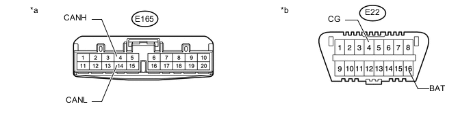
Text in Illustration *1 No. 10 CAN Junction Connector - - *a Rear view of wire harness connector
(to No. 10 CAN Junction Connector)
*b Front view of DLC3 -
Measure the resistance according to the value(s) in the table below.
Standard Resistance Tester Connection Condition Specified Condition K59-1 (CANH) - K59-2 (CANL) Cable disconnected from negative (-) battery terminal 200 Ω or higher K59-1 (CANH) - E22-4 (CG) Cable disconnected from negative (-) battery terminal 200 Ω or higher K59-2 (CANL) - E22-4 (CG) Cable disconnected from negative (-) battery terminal 200 Ω or higher K59-1 (CANH) - E22-16 (BAT) Cable disconnected from negative (-) battery terminal 6 kΩ or higher K59-2 (CANL) - E22-16 (BAT) Cable disconnected from negative (-) battery terminal 6 kΩ or higher
OK
REPLACE NO. 10 CAN JUNCTION CONNECTOR
NG
-
-
CONNECT CONNECTOR
-
Reconnect the K59 No. 10 CAN junction connector.
NEXT
-
-
CHECK CAN BUS WIRE (REAR TELEVISION CAMERA ASSEMBLY - NO. 10 CAN JUNCTION CONNECTOR)
-
Disconnect the rear television camera assembly connector.
-
Measure the resistance according to the value(s) in the table below.
Standard Resistance Tester Connection Condition Specified Condition S28-4 (CANH) - S28-1 (CANL) Cable disconnected from negative (-) battery terminal 54 to 69 Ω S28-4 (CANH) - E22-4 (CG) Cable disconnected from negative (-) battery terminal 200 Ω or higher S28-1 (CANL) - E22-4 (CG) Cable disconnected from negative (-) battery terminal 200 Ω or higher S28-4 (CANH) - E22-16 (BAT) Cable disconnected from negative (-) battery terminal 6 kΩ or higher S28-1 (CANL) - E22-16 (BAT) Cable disconnected from negative (-) battery terminal 6 kΩ or higher
OK
REPLACE REAR TELEVISION CAMERA ASSEMBLY Click here
NG
REPAIR OR REPLACE CAN BUS BRANCH WIRE OR CONNECTOR (REAR TELEVISION CAMERA ASSEMBLY - NO. 10 CAN JUNCTION CONNECTOR)
-
-
CHECK CAN BUS WIRE (NO. 8 CAN JUNCTION CONNECTOR - SIDE TELEVISION CAMERA ASSEMBLY RH)
-
Disconnect the No. 8 CAN junction connector.
Text in Illustration *a Front view of wire harness connector
(to No. 8 CAN Junction Connector)
*b Front view of DLC3 -
Measure the resistance according to the value(s) in the table below.
Standard Resistance Tester Connection Condition Specified Condition E165-5 (CANH) - E165-15 (CANL) Cable disconnected from negative (-) battery terminal 200 Ω or higher E165-5 (CANH) - E22-4 (CG) Cable disconnected from negative (-) battery terminal 200 Ω or higher E165-15 (CANL) - E22-4 (CG) Cable disconnected from negative (-) battery terminal 200 Ω or higher E165-5 (CANH) - E22-16 (BAT) Cable disconnected from negative (-) battery terminal 6 kΩ or higher E165-15 (CANL) - E22-16 (BAT) Cable disconnected from negative (-) battery terminal 6 kΩ or higher
OK
REPLACE NO. 8 CAN JUNCTION CONNECTOR
NG
-
-
CONNECT CONNECTOR
-
Reconnect the E165 No. 8 CAN junction connector.
NEXT
-
-
CHECK CAN BUS WIRE (SIDE TELEVISION CAMERA ASSEMBLY RH - NO. 8 CAN JUNCTION CONNECTOR)
-
Disconnect the side television camera assembly RH connector.
-
Measure the resistance according to the value(s) in the table below.
Standard Resistance Tester Connection Condition Specified Condition I33-3 (CANH) - I33-14 (CANL) Cable disconnected from negative (-) battery terminal 54 to 69 Ω I33-3 (CANH) - E22-4 (CG) Cable disconnected from negative (-) battery terminal 200 Ω or higher I33-14 (CANL) - E22-4 (CG) Cable disconnected from negative (-) battery terminal 200 Ω or higher I33-3 (CANH) - E22-16 (BAT) Cable disconnected from negative (-) battery terminal 6 kΩ or higher I33-14 (CANL) - E22-16 (BAT) Cable disconnected from negative (-) battery terminal 6 kΩ or higher
OK
REPLACE SIDE TELEVISION CAMERA ASSEMBLY RH Click here
NG
REPAIR OR REPLACE CAN BUS BRANCH WIRE OR CONNECTOR (SIDE TELEVISION CAMERA ASSEMBLY RH - NO. 8 CAN JUNCTION CONNECTOR)
-
-
CHECK CAN BUS WIRE (NO. 8 CAN JUNCTION CONNECTOR - FRONT TELEVISION CAMERA ASSEMBLY)
-
Disconnect the No. 8 CAN junction connector.
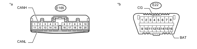
Text in Illustration *a Front view of wire harness connector
(to No. 8 CAN Junction Connector)
*b Front view of DLC3 -
Measure the resistance according to the value(s) in the table below.
Standard Resistance Tester Connection Condition Specified Condition E165-2 (CANH) - E165-12 (CANL) Cable disconnected from negative (-) battery terminal 200 Ω or higher E165-2 (CANH) - E22-4 (CG) Cable disconnected from negative (-) battery terminal 200 Ω or higher E165-12 (CANL) - E22-4 (CG) Cable disconnected from negative (-) battery terminal 200 Ω or higher E165-2 (CANH) - E22-16 (BAT) Cable disconnected from negative (-) battery terminal 6 kΩ or higher E165-12 (CANL) - E22-16 (BAT) Cable disconnected from negative (-) battery terminal 6 kΩ or higher
OK
REPLACE NO. 8 CAN JUNCTION CONNECTOR
NG
-
-
CONNECT CONNECTOR
-
Reconnect the E165 No. 8 CAN junction connector.
NEXT
-
-
CHECK CAN BUS WIRE (FRONT TELEVISION CAMERA ASSEMBLY - NO. 8 CAN JUNCTION CONNECTOR)
-
Disconnect the front television camera assembly connector.
-
Measure the resistance according to the value(s) in the table below.
Standard Resistance Tester Connection Condition Specified Condition s1-4 (CANH) - s1-1 (CANL) Cable disconnected from negative (-) battery terminal 54 to 69 Ω s1-4 (CANH) - E22-4 (CG) Cable disconnected from negative (-) battery terminal 200 Ω or higher s1-1 (CANL) - E22-4 (CG) Cable disconnected from negative (-) battery terminal 200 Ω or higher s1-4 (CANH) - E22-16 (BAT) Cable disconnected from negative (-) battery terminal 6 kΩ or higher s1-1 (CANL) - E22-16 (BAT) Cable disconnected from negative (-) battery terminal 6 kΩ or higher
OK
REPLACE FRONT TELEVISION CAMERA ASSEMBLY Click here
NG
REPAIR OR REPLACE CAN BUS BRANCH WIRE OR CONNECTOR (FRONT TELEVISION CAMERA ASSEMBLY - NO. 8 CAN JUNCTION CONNECTOR)
-
-
CHECK CAN BUS WIRE (NO. 8 CAN JUNCTION CONNECTOR - SIDE TELEVISION CAMERA ASSEMBLY LH)
-
Disconnect the No. 8 CAN junction connector.
Text in Illustration *a Front view of wire harness connector
(to No. 8 CAN Junction Connector)
*b Front view of DLC3 -
Measure the resistance according to the value(s) in the table below.
Standard Resistance Tester Connection Condition Specified Condition E165-4 (CANH) - E165-14 (CANL) Cable disconnected from negative (-) battery terminal 200 Ω or higher E165-4 (CANH) - E22-4 (CG) Cable disconnected from negative (-) battery terminal 200 Ω or higher E165-14 (CANL) - E22-4 (CG) Cable disconnected from negative (-) battery terminal 200 Ω or higher E165-4 (CANH) - E22-16 (BAT) Cable disconnected from negative (-) battery terminal 6 kΩ or higher E165-14 (CANL) - E22-16 (BAT) Cable disconnected from negative (-) battery terminal 6 kΩ or higher
OK
REPLACE NO. 8 CAN JUNCTION CONNECTOR
NG
-
-
CONNECT CONNECTOR
-
Reconnect the No. 8 CAN junction connector.
NEXT
-
-
CHECK CAN BUS WIRE (SIDE TELEVISION CAMERA ASSEMBLY LH - NO. 8 CAN JUNCTION CONNECTOR)
-
Disconnect the side television camera assembly LH connector.
-
Measure the resistance according to the value(s) in the table below.
Standard Resistance Tester Connection Condition Specified Condition I35-3 (CANH) - I35-14 (CANL) Cable disconnected from negative (-) battery terminal 108 to 132 Ω I35-3 (CANH) - E22-4 (CG) Cable disconnected from negative (-) battery terminal 200 Ω or higher I35-14 (CANL) - E22-4 (CG) Cable disconnected from negative (-) battery terminal 200 Ω or higher I35-3 (CANH) - E22-16 (BAT) Cable disconnected from negative (-) battery terminal 6 kΩ or higher I35-14 (CANL) - E22-16 (BAT) Cable disconnected from negative (-) battery terminal 6 kΩ or higher
OK
REPLACE SIDE TELEVISION CAMERA ASSEMBLY LH Click here
NG
REPAIR OR REPLACE CAN BUS BRANCH WIRE OR CONNECTOR (SIDE TELEVISION CAMERA ASSEMBLY LH - NO. 8 CAN JUNCTION CONNECTOR)
-