LEXUS PARKING ASSIST-SENSOR SYSTEM TERMINALS OF ECU
-
CHECK CLEARANCE WARNING ECU ASSEMBLY

-
Disconnect the F92 clearance warning ECU assembly connector.
-
Measure the voltage and resistance according to value(s) in the table below.
Terminal No. (Symbol) Wiring Color Terminal Description Condition Specified Condition F92-9 (CLSW) - F92-30 (E) W - BR Main switch assembly (clearance sonar main switch) power source signal Engine switch on (IG), main switch assembly (clearance sonar main switch) on 11 to 14 V Engine switch on (IG), main switch assembly (clearance sonar main switch) off Below 1 V F92-1 (IG) - F92-30 (E) B - BR IG power source signal Engine switch on (IG) 11 to 14 V Engine switch off Below 1 V F92-30 (E) - Body ground BR - Body ground ECU ground Always Below 1 Ω -
Reconnect the F92 clearance warning ECU assembly connector.
-
Measure the voltage and waveform according to value(s) in the table below.
Terminal No. (Symbol) Wiring Color Terminal Description Condition Specified Condition F92-22 (BOR) - F92-23 (E1) R - GR Rear ultrasonic sensor circuit power source Engine switch off Below 1 V Engine switch on (IG), main switch assembly (clearance sonar main switch) on 7.2 to 8.8 V F92-8 (SOF) - F92-6 (E5) LG - R No. 1 ultrasonic sensor communication signal Engine switch on (IG), main switch assembly (clearance sonar main switch) on Waveform 1 F92-14 (CBZ) - F92-13 (EF) G - L No. 1 clearance warning buzzer signal Buzzer not sounding Below 1 V Buzzer sounding Waveform 2 F92-4 (BOF) - F92-6 (E5) GR - R No. 1 ultrasonic sensor circuit power source Engine switch on (IG), main switch assembly (clearance sonar main switch) on 7.2 to 8.8 V Engine switch off Below 1 V F92-24 (SOR) - F92-23 (E1) LG - GR Rear ultrasonic sensor communication signal Engine switch on (IG), main switch assembly (clearance sonar main switch) on Waveform 3 -
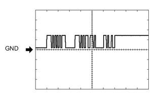
Using an oscilloscope, check waveform 1.
Waveform 1 (Reference) Item Content Terminal No. (Symbol) F92-8 (SOF) - F92-6 (E5) Tool Setting 2 V/DIV., 1 msec./DIV. Condition Engine switch on (IG), main switch assembly (clearance sonar main switch) on -
Using an oscilloscope, check waveform 2.
Waveform 2 (Reference) Item Content Terminal No. (Symbol) F92-14 (CBZ) - F92-13 (EF) Tool Setting 5 V/DIV., 1 msec./DIV. Condition Buzzer sounding Note
The waveform amplitude varies depending on the volume setting.
-
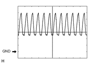
Using an oscilloscope, check waveform 3.
Waveform 1 (Reference) Item Content Terminal No. (Symbol) F92-24 (SOR) - F92-23 (E1) Tool Setting 5 V/DIV., 1 ms./DIV. Condition Engine switch on (IG), main switch assembly (clearance sonar main switch) on
-