TELEMATICS TRANSCEIVER INSTALLATION
PROCEDURE
-
INSTALL NO. 1 TELEPHONE BRACKET
-
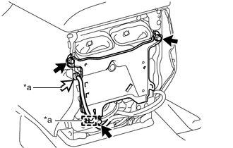
*a w/ Antenna Divider w/o Antenna Divider
-
Install the No. 1 telephone bracket with the 3 bolts.
- Torque:
- 8.5 N*m { 87 kgf*cm, 75 in.*lbf }
-
-
w/ Antenna Divider
-
Install the No. 1 telephone bracket with the 3 bolts.
- Torque:
- 8.5 N*m { 87 kgf*cm, 75 in.*lbf }
-
Attach the clamp and connect the connector.
-
-
-
INSTALL NO. 2 TELEPHONE BRACKET (w/ Telematics Transceiver for G-BOOK)
-
Install the telephone bracket RH to the telematics transceiver with the 2 screws.
-
Install the telephone bracket LH to the telematics transceiver with the 2 screws.
-
-
INSTALL MAYDAY BATTERY (w/ Telematics Transceiver except G-BOOK)
-
INSTALL TELEMATICS TRANSCEIVER
-
w/ Telematics Transceiver except G-BOOK
-
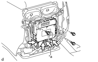
*a w/ Antenna Divider Install the telematics transceiver with the 3 screws.
-
Connect the connectors.
-
-
w/ Telematics Transceiver for G-BOOK
-
Install the telematics transceiver with bracket with the 3 screws.
-
Connect the connectors.
-
-
-
INSTALL REAR CONSOLE END PANEL SUB-ASSEMBLY
-
CONNECT CABLE TO NEGATIVE BATTERY TERMINAL
Note
When disconnecting the cable, some systems need to be initialized after the cable is reconnected Click here.
-
INSTALL UPPER RADIATOR SUPPORT SEAL
-
CHECK SRS WARNING LIGHT
-
Check the SRS warning light Click here.
-
-
PERFORM REGISTRATION
-
w/ Telematics Transceiver for G-BOOK
Perform registration Click here.
Note
When replacing the telematics transceiver, perform registration.
-
w/ Telematics Transceiver except G-BOOK
Perform registration Click here.
Note
When replacing the telematics transceiver, perform registration.
-