TELEMATICS SYSTEM SYSTEM DESCRIPTION
-
TELEMATICS SYSTEM OUTLINE
-
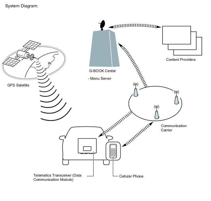
The telematics system is a telematics service that links the vehicle and G-BOOK network (provides information from the G-BOOK center or content providers).
-
To use the telematics system, it is necessary to connect the telematics transceiver (Data Communication Module [DCM]) to the multi-media module receiver assembly.
Tech Tips
For vehicles with a telematics transceiver, the telematics system cannot be used over a "Wi-Fi" connection.
-
The user needs to follow the instructions on the accessory meter assembly screen to start using the telematics system service after applying for the service at a dealership.
-
-
FUNCTION OF MAIN COMPONENTS
Component Function Map Light Assembly
-
Emergency Call Switch
When the emergency call switch is pressed, a switch signal is sent to the telematics transceiver.
(When a manual maintenance check or manual emergency call is performed.)
LED Indicator Light Green
-
Turns on for 5 seconds after the engine switch is turned on (ACC).
-
Turns on when the system is under a service contract and operating normally.
-
Blinks during an emergency call.
-
Blinks during a manual maintenance check.
-
Turns off when the system is malfunctioning.
Red
-
Turns on for 5 seconds after the engine switch is turned on (ACC).
-
Turns on when the telematics transceiver is not within the service area.
-
Blinks when an emergency call is made while the system is still malfunctioning.
-
Turns off when the system is operating normally.
-
Blinks when the mayday battery needs to be replaced.
-
Blinks when in diagnostic mode to indicate a DTC.
Map Light Assembly
-
Telephone Microphone Assembly
-
When the operator service is used: Sends the microphone voice signal to the multi-media module receiver assembly.
-
When an emergency call is made: Sends the microphone voice signal to the telematics transceiver.
Telephone Antenna Assembly Sends and receives the data and voice signals used for the G-BOOK through a communication network. Telematics Transceiver
-
Uses the telephone antenna assembly to send and receive the data and voice signals used for the G-BOOK through a communication network.
-
When the operator service is used: Sends the received voice signal to the multi-media module receiver assembly.
-
When the operator service is used: Sends the sent voice signal from the multi-media module receiver assembly to the telephone antenna assembly.
-
When an emergency call is made: Sends the received voice signal to the vehicle speakers.
-
When an emergency call is made: Receives the sent voice signal from the telephone microphone assembly.
-
When an emergency call is made: Sends a mute signal to the stereo component amplifier assembly. (Mute function becomes active during the call.)
-
When an emergency call is made: Sends vehicle location information to the G-BOOK center.
-
When a warning occurs, the telematics transceiver receives a warning ON signal from the combination meter assembly via CAN communication and sends it to the G-BOOK center.
-
When the theft deterrent system is activated, the telematics transceiver sends information that the security horn has sounded to the G-BOOK center.
Mayday Battery (Back-up Battery)
-
When an automatic emergency call is performed, the mayday battery provides power to the DCM.
-
When a manual emergency call is made, the mayday battery is not used as the power source.
-
The mayday battery conducts a self-diagnosis every time the engine switch is turned on (IG), and after an automatic emergency call or manual emergency call is made, and the result is sent to the DCM.
Navigation Antenna Assembly Receives GPS radio waves and sends them to the multi-media module receiver assembly. Main Body ECU (Multiplex Network Body ECU) Sends a security horn sounding signal to the telematics transceiver when the theft deterrent system is activated. Multi-media module receiver assembly
-
Sends and receives the data used for the G-BOOK to and from the telematics transceiver using a telematics data signal.
-
When the operator service is used: Sends the sent voice signal from the telephone microphone assembly to the telematics transceiver.
-
When the operator service is used: Sends the received voice signal from the telematics transceiver to the stereo component amplifier assembly using a MOST signal.
-
Sends vehicle location information to the telematics transceiver.
Stereo Component Amplifier Assembly Receives the received voice signal sent from the multi-media module receiver assembly as a sound signal and outputs it as sound from the speakers via the telematics transceiver.
(When the operator service is used.)
Center Airbag Sensor Assembly Sends an activation signal to the telematics transceiver when airbags deploy.
(An automatic emergency call is made.)
Combination Meter Assembly Sends a warning signal to the telematics transceiver via CAN communication when a warning occurs. -
-
DEVICE USED FOR TELEMATICS SYSTEM COMMUNICATION
-
The telematics transceiver is used for data communication or emergency call service telephone calls and operator service telephone calls.
-
The hands-free function does not use the telematics transceiver. A user's "Bluetooth" compatible cellular phone needs to be used.
-
Perform the following if the device used for telematics system communication is replaced.
Tech Tips
-
If the multi-media module receiver assembly or the telematics transceiver is replaced on vehicles that do not have a contract for the G-BOOK, perform vehicle contract setting.
-
If the multi-media module receiver assembly or the telematics transceiver is replaced on vehicles that have a contract for the G-BOOK, perform the vehicle contract setting and the procedure to resume the G-BOOK to start the emergency call service.
-
-
-
G-BOOK ID OUTLINE
-
On this model, the multi-media module receiver assembly functions as the G-BOOK device.
-
The multi-media module receiver assembly has a serial number (G-BOOK ID) which can be used to determine the individual device when servicing.
-
-
MAYDAY ID OUTLINE
-
On this model, the telematics transceiver functions as the emergency call service device to perform emergency calls.
-
The telematics transceiver has a serial number (mayday ID) which can be used to identify the individual device when servicing.
-
-
DATA COMMUNICATION MODULE (DCM) OUTLINE
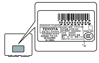
Text in Illustration *a DCM ID
-
The G-BOOK device uses the telematics transceiver to provide access to the network service.
-
The telematics transceiver has a DCM ID (printed on the label attached to the telematics transceiver).
-
As is the case with cellular phones, the telematics transceiver has a phone number.
-
-
G-BOOK SUPPORT CENTER OUTLINE
-
The G-BOOK support center provides members with opportunities to ask questions and information necessary for troubleshooting.
G-BOOK Support Center Main Service Outline Answering questions about the telematics system Answers questions from customers about the telematics system Contracting or canceling the G-BOOK Performs procedures to make or cancel a contract for customers Confirming server or communication conditions Confirms the G-BOOK center condition Re-registering a G-BOOK device or telematics transceiver Performs procedures for re-registration when the G-BOOK device or telematics transceiver is replaced Answering questions about a manual maintenance check for the emergency call service Answers questions when a manual maintenance check for the emergency call service has not completed normally
-
-
REMOTE SERVICE (SAFETY & SECURITY FUNCTION AND REMOTE MAINTENANCE SERVICE) OUTLINE
-
Remote service (safety and security function and remote maintenance service)
-
The telematics transceiver (Data Communication Module [DCM]) sends the vehicle status to the G-BOOK center, which then sends the vehicle status to each services network (dealer, etc.) or each customer's cellular phone, enabling the vehicle status to be checked from a remote location.
Tech Tips
The remote service has functions such as the safety and security function (vehicle status alerts, vehicle status report, alarm notification) and remote maintenance service (warning notification).
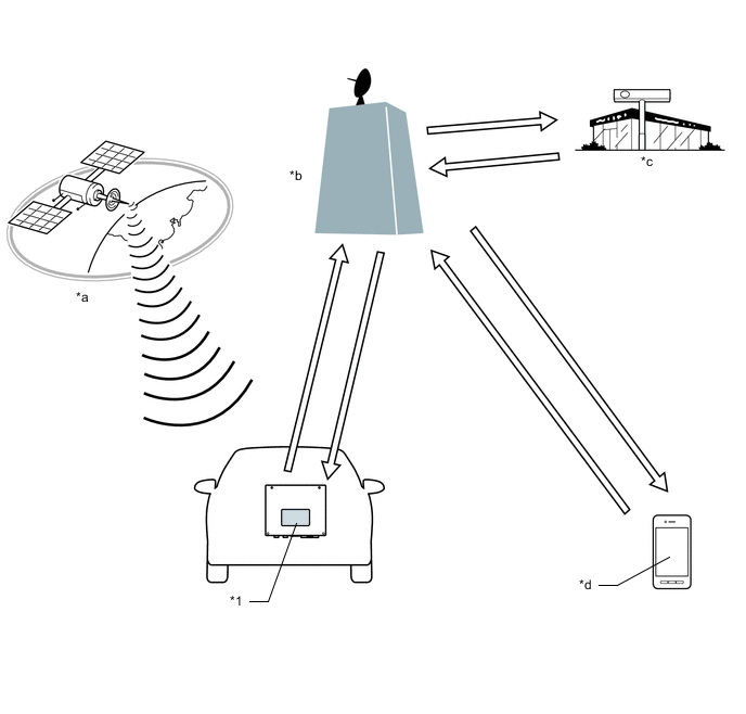
Text in Illustration *1 Telematics Transceiver (Data Communication Module [DCM]) - - *a GPS Satellite *b G-BOOK Center *c Each Services Network (Dealer, etc.) *d Customer's Cellular Phone
-
-
-
SAFETY & SECURITY FUNCTION OUTLINE
-
Vehicle status alerts
-
Once a fixed amount of time elapses after completing vehicle device operations such as turning the engine switch off and locking the doors, the vehicle status is sent to the G-BOOK center.
When the vehicle status alerts delivery conditions are met, vehicle status alerts notification emails are delivered to the specified email address of the customer.
Vehicle Status Alerts Delivery Conditions Vehicle status alerts email delivery conditions When the following conditions are met according to the information stored at the G-BOOK center:
-
Hood, back door and all doors closed
-
Electrical key transmitter not detected inside vehicle
-
When one or more of the following occurs: Doors unlock, hazard lights flash, headlights illuminate, clearance light illuminates, windows open or sliding roof opens.
Note
-
To prevent vehicle status alerts emails from being delivered to customers when inspections and repairs are performed, set the telematics system to communication function restraint mode Click here.
-
After removal and installation of the battery, emails are not delivered until the engine switch is turned on (ACC).
-
Even when the electrical key transmitter is inside the interior key detection area, the electrical key transmitter may not be detected if inside a metallic bag, the battery is depleted, etc.
-
Even when the electrical key transmitter is outside the vehicle, the electrical key transmitter may be determined to be inside the vehicle depending on whether the entry and start system is canceled, where the electrical key transmitter is placed, etc.
Tech Tips
Cancel/temporary stop settings for the vehicle status alerts can be operated by the customer via the G-BOOK on-vehicle screen, G-BOOK site or G-BOOK mobile site.
-
-
-
Vehicle status report
-
Once a fixed amount of time elapses after completing vehicle device operations such as turning the engine switch off and locking the doors, the vehicle status report function sends the vehicle status to the G-BOOK center. Afterward, the vehicle status can be checked on the customer's cellular phone.
Note
-
Before performing inspections and repairs, prevent the vehicle status from updating by setting the telematics system to communication function restraint mode Click here.
-
After removal and installation of the battery, the vehicle status report condition is not updated until the engine switch is turned on (ACC).
-
When the entry and start system is canceled, even if the electrical key transmitter is outside the vehicle, the system may determine that the key is inside the vehicle.
-
-
-
Alarm notification
-
When the security horn warning operates, the customer is notified via telephone and an email delivered to their specified email address from the service center.
Note
-
Take care to prevent alarm notifications being sent during work.
-
When performing inspections and repairs that may cause alarm notifications to be sent, make sure to tell the customer in advance that they may receive alarm notification emails or telephone calls.
Tech Tips
The alarm notification cancel setting can be operated by the customer via the G-BOOK onvehicle screen, G-BOOK site or G-BOOK mobile site.
-
-
-
-
COMMUNICATION SYSTEM
-
USB Outline
-
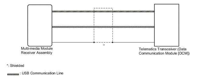
Telematics system components communicate with each other via USB communication.
Tech Tips
If a short or open occurs in a USB communication line, communication will be interrupted and the system will not operate normally.
-
-
AVC-LAN Outline
Tech Tips
Refer to System Description of Navigation System Click here.
-
MOST Network Outline
Tech Tips
Refer to System Description of Navigation System Click here.
-
CAN Communication Outline
Tech Tips
Refer to System Description of Navigation System Click here.
-
-
DIAGNOSTIC FUNCTION OUTLINE
-
The telematics system has a diagnostic function (the result will be displayed on the master unit or GTS).
-
-
DIAGNOSIS DISPLAY DETAILED DESCRIPTION
Tech Tips
This section contains a detailed description of displays in diagnostic mode.
-
Enter diagnostic mode Click here.
-
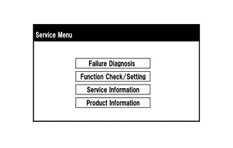
Select "Service Information" on the "Service Menu" screen.
-
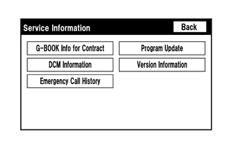
"Service Information" Screen
Screen Description Display Content G-BOOK Info for Contract The G-BOOK ID, flag information, etc. are displayed. DCM Information The ID, contract information, maintenance check date, etc. which are related to the emergency call service are displayed. Emergency Call History The history (date and condition) of emergency calls is displayed Click here.
-
Select "G-BOOK Info for Contract" on the "Service Information" screen.
-
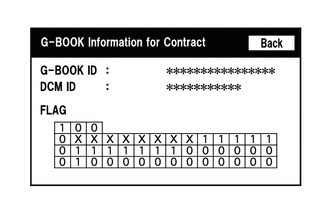
"G-BOOK Information for Contract" Screen
Screen Description Display Content G-BOOK ID The G-BOOK ID of the multi-media module receiver assembly is displayed. DCM ID The 11-digit serial number of the telematics transceiver is displayed. FLAG The G-BOOK contract flag or service flag of the multi-media module receiver assembly is displayed. -
Select "DCM Information" on the "Service Information" screen.
-
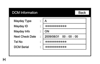
"DCM Information" Screen
Screen Description Display Content Mayday Type The type of installed emergency call service device is displayed (on this model, "A" (airbag-linked type) is displayed). Mayday ID The ID of the installed emergency call service device is displayed. Mayday Info The emergency call service contract condition is displayed as follows:
-
ON: Contract has been made and membership has been registered
-
OFF: Contract has been made but membership has not been registered
-
NO CONT: Not contracted
Next Check Date The date on which the automatic maintenance check will be performed next is displayed. Tel No
-
The phone number of the telematics transceiver is displayed.
-
"NO DCM" is displayed when the telematics transceiver is not connected to the multi-media module receiver assembly.
DCM Serial
-
The 11-digit serial number of the telematics transceiver is displayed (DCM ID).
-
"NO DCM" is displayed when the telematics transceiver is not connected to the multi-media module receiver assembly.
-
-
-
MAYDAY BATTERY OUTLINE
-
As the mayday battery is a non-rechargeable (primary) battery, it cannot be recharged.
-
When it is time to replace the mayday battery, the emergency call switch red indicator will come on.
The DCM will also store a DTC.
Note
After an automatic emergency call is performed, the mayday battery must be replaced with a new one.
-
-
COMMUNICATION FUNCTION RESTRAINT OPERATION
Note
-
Set the vehicle to "Communication function restraint" before performing inspections and repairs such as the removal and installation of parts, simulation tests, confirmation driving patterns, etc., which output warning displays and DTCs so that the G-BOOK center will not incorrectly recognize the output warnings and DTCs. Doing so also prevents the delivery of vehicle status alerts emails to customers according to vehicle operations performed and the vehicle status while at the workshop, and the updating of the vehicle status which can be checked via the vehicle status report function.
-
Communication function restraint mode can be entered by using the GTS or operating the multi-display.
Tech Tips
-
When a warning is generated by a vehicle malfunction, the warning notification function sends a warning display signal from the combination meter assembly to the G-BOOK center via the G-BOOK onboard device.
-
Updates to the vehicle status, which can be checked by the delivery of vehicle status alerts emails and the vehicle status report, are based on the vehicle status sent to the G-BOOK center once a fixed amount of time elapses after completing vehicle device operations such as turning the engine switch off.
-
Immediately after entering communication function restraint mode using the GTS or when starting the navigation system by turning the engine switch from off to on (ACC), the communication function restraint mode can be canceled/resumed from the displayed communication function suspension screen.
-
Communication function restraint
Tech Tips
To cancel warning notification restraint mode, turn the engine switch off and on (IG) to display the service mode screen and cancel warning notification restraint mode.
-
Communication function restraint setting method (Using the multi-display)
-
Enter diagnostic mode of navigation system Click here.
-
Once the above operation(s) are performed, the telematics system enters communication function restraint mode.
-
-
Communication function restraint setting method (Using the GTS)
-
Turn the engine switch off.
-
Connect the GTS to the DLC3.
-
Start the engine.
-
Turn the GTS on.
-
Enter the following menus: Powertrain / Engine and ECT / Trouble Codes.
-
Once the above operation(s) are performed, the telematics system enters communication function restraint mode.
-
-
-