STEREO COMPONENT AMPLIFIER INSTALLATION
PROCEDURE
-
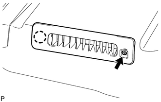
INSTALL NO. 2 AMPLIFIER BRACKET
-
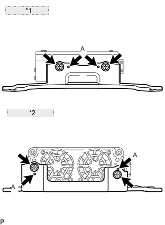
*1 for 9 Speakers: *2 for 19 Speakers: Set the aligning protrusions of the bracket, labeled A, into the holes of the amplifier.
-
Install the bracket with the 2 screws labeled B.
- Torque:
- 3.0 N*m { 30 kgf*cm, 26 in.*lbf }
-
-
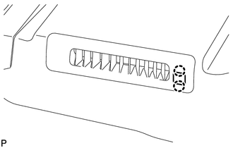
INSTALL NO. 1 AMPLIFIER BRACKET
-
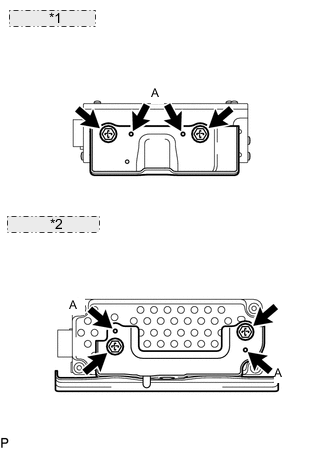
*1 for 9 Speakers: *2 for 19 Speakers: Set the aligning protrusions of the bracket, labeled A, into the holes of the amplifier.
-
Install the bracket with the 2 screws labeled B.
- Torque:
- 3.0 N*m { 30 kgf*cm, 26 in.*lbf }
-
-
INSTALL AMPLIFIER COVER (for 9 Speakers)
-
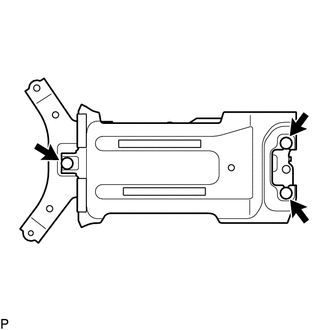
Attach the 3 clips to install the cover.
-
-
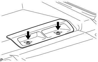
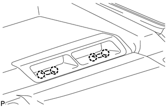
INSTALL STEREO COMPONENT AMPLIFIER ASSEMBLY WITH BRACKET
-
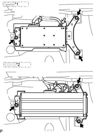
*1 for 9 Speakers: *2 for 19 Speakers: Install the amplifier with the 3 bolts.
- Torque:
- 7.5 N*m { 76 kgf*cm, 66 in.*lbf }
-
Connect the connectors.
-
-
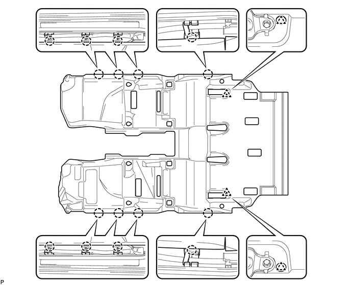
INSTALL FRONT FLOOR CARPET ASSEMBLY
-
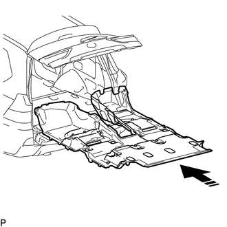
Open the tail gate and back door, insert the carpet into the cabin from the rear, and install it to the floor.
-
Attach the 2 clips and 8 claws.
-
-
INSTALL REAR CONSOLE BOX SUB-ASSEMBLY (w/o Cool Box)
-
Install the rear console box Click here.
-
-
INSTALL COOLING BOX ASSEMBLY (w/ Cool Box)
-
Install the cooling box Click here.
-
-
INSTALL REAR NO. 2 SEAT PROTECTOR
-
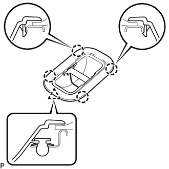
Attach the 4 clips and claw to install the protector.
Tech Tips
Use the same procedures to install the protector on the other side.
-
-
INSTALL REAR NO. 1 SEAT PROTECTOR
-
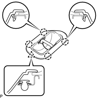
Attach the 4 clips and claw to install the protector.
Tech Tips
Use the same procedures to install the protector on the other side.
-
-
INSTALL REAR AIR DUCT GUIDE
Tech Tips
Use the same procedures for both sides.
-
Attach the claw to install the guide.
-
Install the screw.
-
-
INSTALL AIR DUCT PLUG
-
Attach the 2 claws to install the plug.
Tech Tips
Use the same procedures for both sides.
-
-
INSTALL AIR HEATER GUIDE
-
Install the guide with the 2 screws.
Tech Tips
Use the same procedures for both sides.
-
-
INSTALL NO. 2 AIR DUCT PLUG
-
Attach the 4 claws to install the 2 plugs.
Tech Tips
Use the same procedures for both sides.
-
-
INSTALL REAR DOOR SCUFF PLATE LH
-
INSTALL REAR DOOR SCUFF PLATE RH
-
INSTALL REAR STEP COVER
-
INSTALL COWL SIDE TRIM BOARD RH
-
INSTALL NO. 2 INSTRUMENT PANEL UNDER COVER SUB-ASSEMBLY
-
INSTALL COWL SIDE TRIM BOARD LH
-
INSTALL NO. 1 INSTRUMENT PANEL UNDER COVER SUB-ASSEMBLY
-
INSTALL FRONT DOOR SCUFF PLATE LH
-
INSTALL FRONT DOOR SCUFF PLATE RH
-
INSTALL INSTRUMENT SIDE PANEL RH
-
INSTALL INSTRUMENT SIDE PANEL LH
-
INSTALL REAR NO. 1 SEAT ASSEMBLY RH
-
INSTALL REAR NO. 3 SEAT CUSHION HINGE COVER
-
INSTALL REAR NO. 1 SEAT CUSHION HINGE COVER
-
INSTALL REAR NO. 4 SEAT CUSHION HINGE COVER
-
INSTALL REAR NO. 2 SEAT CUSHION HINGE COVER
-
INSTALL REAR NO. 1 SEAT ASSEMBLY LH
-
INSTALL REAR NO. 4 SEAT CUSHION HINGE COVER
-
INSTALL REAR NO. 2 SEAT CUSHION HINGE COVER
-
INSTALL REAR NO. 5 SEAT CUSHION HINGE COVER
-
INSTALL REAR NO. 3 SEAT CUSHION HINGE COVER
-
INSTALL FRONT SEAT ASSEMBLY RH
-
Install the front seat assembly RH Click here.
-
-
INSTALL FRONT SEAT ASSEMBLY LH
-
Install the front seat assembly LH Click here.
-
-
CONNECT CABLE TO NEGATIVE BATTERY TERMINAL
Note
When disconnecting the cable, some systems need to be initialized after the cable is reconnected Click here.
-
INSTALL UPPER RADIATOR SUPPORT SEAL
-
CHECK SRS WARNING LIGHT
-
Check the SRS warning light Click here.
-