STEERING COLUMN ASSEMBLY INSTALLATION
CAUTION / NOTICE / HINT
Tech Tips
-
Use the same procedure for RHD and LHD vehicles.
-
The procedure listed below is for LHD vehicles.
PROCEDURE
-
CONNECT NO. 2 STEERING INTERMEDIATE SHAFT
-
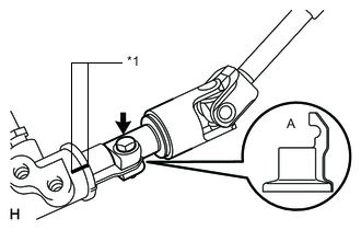
*1 Matchmark Align the part of the dust cover labeled A with the No. 2 steering intermediate shaft, and install the No. 2 steering intermediate shaft assembly to the steering link assembly.
-
Install the bolt.
- Torque:
- 35 N*m { 357 kgf*cm, 26 ft.*lbf }
Note
Be careful not to damage the dust cover.
-
-
INSTALL STEERING COLUMN HOLE COVER SUB-ASSEMBLY
-
Install the 4 bolts and nut.
- Torque:
- 5.0 N*m { 51 kgf*cm, 44 in.*lbf }
Tech Tips
Install the steering intermediate shaft assembly from the inside of the vehicle.
-
Install the clamp to the steering column hole cover.
-
-
INSTALL STEERING ACTUATOR ASSEMBLY
-
INSTALL STEERING COLUMN ASSEMBLY
-
Install the steering column with the 4 nuts.
- Torque:
- 26 N*m { 265 kgf*cm, 19 ft.*lbf }
-
-
INSTALL NO. 3 AIR DUCT SUB-ASSEMBLY
-
CONNECT WIRE HARNESS PROTECTOR AND WIRE HARNESS
-
Attach the 2 claws and 2 harness clamps and connect the wire harness protector and wire harness.
-
-
INSTALL LOWER NO. 1 INSTRUMENT PANEL AIRBAG ASSEMBLY
-
INSTALL COMBINATION SWITCH ASSEMBLY WITH SPIRAL CABLE SUB-ASSEMBLY
-
Attach the 3 claws to install the combination switch assembly with spiral cable sub-assembly to the steering column assembly.
-
Connect connectors to the combination switch assembly with spiral cable sub-assembly.
-
-
INSTALL UPPER STEERING COLUMN COVER
-
Attach the 2 guide pins and claw.
-
Attach the 4 clips and 2 claws to install the upper steering column cover onto the meter hood spacer.
-
-
INSTALL LOWER STEERING COLUMN COVER
-
Attach the 2 claws to install the lower steering column cover.
Note
Do not damage the tilt and telescopic switch.
-
Install the 3 screws.
-
-
ADJUST SPIRAL CABLE
-
INSTALL STEERING WHEEL ASSEMBLY
-
CHECK FRONT WHEELS FACING STRAIGHT AHEAD
-
INSTALL FRONT WHEELS
-
CONNECT CABLE TO NEGATIVE BATTERY TERMINAL
Note
-
Reset the AUTO TILT AWAY function setting to the previous condition by changing the customize parameter Click here.
-
When disconnecting the cable, some systems need to be initialized after the cable is reconnected Click here.
-
-
CHECK SRS WARNING LIGHT
-
PERFORM VARIABLE GEAR RATIO STEERING SYSTEM CALIBRATION