HEATED STEERING WHEEL SYSTEM Steering Wheel does not Heat Up When Heated Steering Wheel Switch is Pressed
DESCRIPTION
Refer to the System Description Click here.
WIRING DIAGRAM
Refer to the System Diagram Click here.
CAUTION / NOTICE / HINT
Tech Tips
-
Inspect the fuses for circuits related to this system before performing the following inspection procedure.
-
The steering vibration and heater ECU and steering wheel heater unit is built into the steering wheel assembly. Therefore, when the steering vibration and heater ECU and/or steering wheel heater unit has a malfunction, replace the steering wheel assembly.
PROCEDURE
-
INSPECT STEERING WHEEL ASSEMBLY (THERMISTOR/HEATER/THERMOSTAT)
-
Disconnect the B steering vibration and heater ECU connector.
-
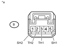
Text in Illustration *a Component without harness connected
(Steering Wheel Assembly)
Measure the resistance according to the value(s) in the table below.
Standard Resistance Tester Connection Condition Specified Condition B-3 (TH1) - B-2 (TH2) 10 to 30°C (50 to 86°F) 4.129 to 8.979 kΩ B-5 (SH1) - B-1 (SH2) 20°C (68°F) 2.43 to 2.89 kΩ
NG 
REPLACE STEERING WHEEL ASSEMBLY Click here
OK 
-
-
INSPECT SPIRAL WITH SENSOR CABLE SUB-ASSEMBLY
-
Check the connectors and cables of the spiral with sensor cable sub-assembly.
OK There are no defects such as scratches, cracks, dents or damage on the connectors or cables. -
Disconnect the E124 and z63 spiral with sensor cable sub-assembly connectors.
-
Measure the resistance according to the value(s) in the table below.
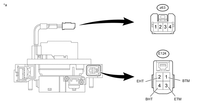
Text in Illustration *a Component without harness connected
(Spiral with Sensor Cable Sub-assembly)
- - Standard Resistance Tester Connection Condition Specified Condition E124-1 (BTM) - z63-2 Always Below 3 Ω E124-3 (BTM) - z63-3 Always Below 3 Ω E124-2 (BTM) - z63-1 Always Below 0.1 Ω E124-4 (BTM) - z63-4 Always Below 0.1 Ω
NG
REPLACE SPIRAL WITH SENSOR CABLE SUB-ASSEMBLY Click here
OK
-
-
CHECK REFRESHING SEAT SWITCH LH (POWER SOURCE)
-
Disconnect the refreshing seat switch LH connector.
-
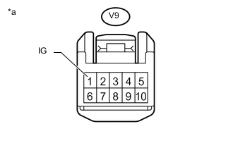
Text in Illustration *a Front view of wire harness connector
(to Refreshing Seat Switch LH)
Measure the voltage according to the value(s) in the table below.
Standard Voltage Tester Connection Switch Condition Specified Condition V9-1 (IG) - Body ground Engine switch on (IG) 11 to 14 V
NG
REPAIR OR REPLACE HARNESS OR CONNECTOR
OK
-
-
CHECK SPIRAL WITH SENSOR CABLE SUB-ASSEMBLY (POWER SOURCE)
-
Disconnect the spiral with sensor cable sub-assembly connector.
-
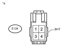
Text in Illustration *a Front view of wire harness connector
(to Spiral with Sensor Cable Sub-assembly)
Measure the voltage according to the value(s) in the table below.
Standard Voltage Tester Connection Switch Condition Specified Condition E124-4 (BHT) - Body ground Engine switch on (IG) 11 to 14 V
NG
REPAIR OR REPLACE HARNESS OR CONNECTOR
OK
-
-
CHECK HARNESS AND CONNECTOR (SPIRAL WITH SENSOR CABLE SUB-ASSEMBLY - BODY GROUND)
-
Disconnect the E124 spiral with sensor cable sub-assembly connector.
-
Measure the resistance according to the value(s) in the table below.
Standard Resistance Tester Connection Condition Specified Condition E124-2 (EHT) - Body ground Always Below 1 Ω
NG
REPAIR OR REPLACE HARNESS OR CONNECTOR
OK
-
-
CHECK REFRESHING SEAT SWITCH LH (IN TERMINAL)
-
Disconnect the E124 spiral with sensor cable sub-assembly connector.
-
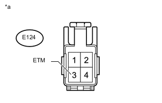
Text in Illustration *a Front view of wire harness connector
(to Spiral with Sensor Cable Sub-assembly)
Measure the voltage according to the value(s) in the table below.
Standard Voltage Tester Connection Condition Specified Condition E124-3 (ETM) - Body ground Engine switch on (IG), steering heater switch off 11 to 14 V Engine switch on (IG), steering heater switch on Below 1 V
OK
REPLACE STEERING WHEEL ASSEMBLY Click here
NG
-
-
CHECK HARNESS AND CONNECTOR (REFRESHING SEAT SWITCH LH - SPIRAL WITH SENSOR CABLE SUB-ASSEMBLY)
-
Disconnect the V9 refreshing seat switch LH connector.
-
Disconnect the E124 spiral with sensor cable sub-assembly connector.
-
Measure the resistance according to the value(s) in the table below.
Standard Resistance Tester Connection Condition Specified Condition V9-8 (IN) - E124-3 (ETM) Always Below 1 Ω V9-8 (IN) or E124-3 (ETM) - Body ground Always 10 kΩ or higher
NG
REPAIR OR REPLACE HARNESS OR CONNECTOR
OK
-
-
CHECK HARNESS AND CONNECTOR (REFRESHING SEAT SWITCH LH - REFRESHING SEAT SWITCH RH)
-
Disconnect the V8 refreshing seat switch LH connector.
-
Disconnect the V10 refreshing seat switch RH connector.
-
Measure the resistance according to the value(s) in the table below.
Standard Resistance Tester Connection Condition Specified Condition V8-16 (SWH) - V10-16 (SWH) Always Below 1 Ω V8-2 (E) - V10-2 (E) Always Below 1 Ω V8-16 (SWH) or V10-16 (SWH) - Body ground Always 10 kΩ or higher V8-2 (E) or V10-2 (E) - Body ground Always 10 kΩ or higher
NG
REPAIR OR REPLACE HARNESS OR CONNECTOR
OK
-
-
CHECK VEHICLE TYPE
-
Check the vehicle type.
Result Proceed to for LHD A for RHD B
B 
INSPECT REFRESHING SEAT SWITCH RH Click here
A
-
-
REPLACE REFRESHING SEAT SWITCH RH
-
Replace the refreshing seat switch RH Click here.
-
When the steering heater switch is pressed, check that the steering wheel becomes warm.
OK Steering wheel becomes warm.
OK
END (REFRESHING SEAT SWITCH RH IS DEFECTIVE)
NG
REPLACE REFRESHING SEAT SWITCH LH Click here
-
-
INSPECT REFRESHING SEAT SWITCH RH
-
Remove the refreshing seat switch RH Click here.
-
Inspect the refreshing seat switch RH Click here.
OK
REPLACE REFRESHING SEAT SWITCH LH Click here
NG
REPLACE REFRESHING SEAT SWITCH RH Click here
-