POWER STEERING SYSTEM(w/ Variable Flow Control Solenoid Valve) Drive Mode Select Switch Circuit
DESCRIPTION
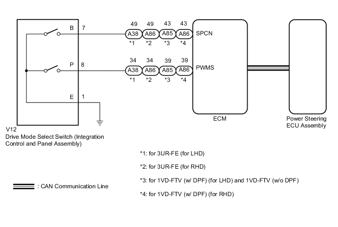
The characteristics of the electronic throttle, PPS and automatic transmission change by operating the drive mode select switch (integration control and panel assembly).
WIRING DIAGRAM
PROCEDURE
-
CHECK CAN COMMUNICATION SYSTEM
-
Check for DTCs.
Result Result Proceed to CAN communication system DTCs are not output A CAN communication system DTCs are output (for LHD) B CAN communication system DTCs are output (for RHD) C
B 
GO TO CAN COMMUNICATION SYSTEM (HOW TOPROCEED WITH TROUBLESHOOTING) Click here
C
GO TO CAN COMMUNICATION SYSTEM (HOW TOPROCEED WITH TROUBLESHOOTING) Click here
A 
-
-
CHECK HARNESS AND CONNECTOR
-
Turn the engine switch off.
-
Disconnect the V12 drive mode select switch (integration control and panel assembly) connector.
-
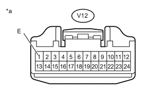
Text in Illustration *a Front view of wire harness connector
(to Drive mode select switch (integration control and panel assembly))
Measure the resistance according to the value(s) in the table below.
Standard Resistance Tester Connection Condition Specified Condition V12-1 (E) - Body ground Always Below 1 Ω
NG
REPAIR OR REPLACE HARNESS OR CONNECTOR
OK
-
-
INSPECT DRIVE MODE SELECT SWITCH (INTEGRATION CONTROL AND PANEL ASSEMBLY)
-
Inspect drive mode select switch (integration control and panel assembly).
-
for AB60F: Click here.
-
for AE80F: Click here.
OK Drive mode select switch (integration control and panel assembly) is normal. Result Result Proceed to OK A NG for AB60F B for AE80F C -
B
REPLACE DRIVE MODE SELECT SWITCH (INTEGRATION CONTROL AND PANEL ASSEMBLY) Click here
C
REPLACE DRIVE MODE SELECT SWITCH (INTEGRATION CONTROL AND PANEL ASSEMBLY) Click here
A
-
-
CHECK HARNESS AND CONNECTOR
-
Reconnect the V12 drive mode select switch (integration control and panel assembly) connector.
-
Disconnect the A38*1, A85*2 or A86*3 ECM connector.
-
*1: for 3UR-FE (for LHD)
-
*2: for 1VD-FTV (w/ DPF) (for LHD) and 1VD-FTV (w/o DPF)
-
*3: for 3UR-FE and 1VD-FTV (w/ DPF) (for RHD)
-
-
Measure the resistance according to the value(s) in the table below.
-
for 3UR-FE
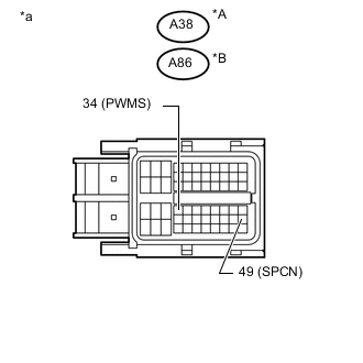
Standard Resistance for LHD Tester Connection Condition Specified Condition A38-34 (PWMS) - Body ground SPORT mode switch being turned and held Below 50 Ω A38-34 (PWMS) - Body ground SPORT mode switch not turned 10 kΩ or higher A38-49 (SPCN) - Body ground NORMAL mode switch being pushed and held Below 50 Ω A38-49 (SPCN) - Body ground NORMAL mode switch not pushed 10 kΩ or higher for RHD Tester Connection Condition Specified Condition A86-34 (PWMS) - Body ground SPORT mode switch being turned and held Below 50 Ω A86-34 (PWMS) - Body ground SPORT mode switch not turned 10 kΩ or higher A86-49 (SPCN) - Body ground NORMAL mode switch being pushed and held Below 50 Ω A86-49 (SPCN) - Body ground NORMAL mode switch not pushed 10 kΩ or higher Text in Illustration *A for LHD *B for RHD *a Front view of wire harness connector
(to ECM)
-
except 3UR-FE
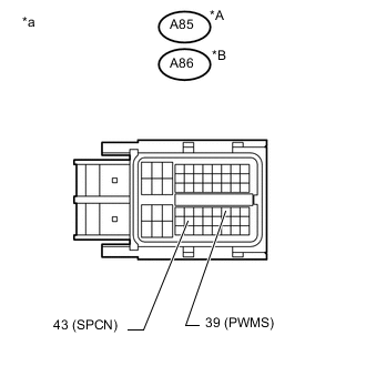
Standard Resistance for 1VD-FTV (w/ DPF) (for LHD) and 1VD-FTV (w/o DPF) Tester Connection Condition Specified Condition A85-39 (PWMS) - Body ground SPORT mode switch being turned and held Below 50 Ω A85-39 (PWMS) - Body ground SPORT mode switch not turned 10 kΩ or higher A85-43 (SPCN) - Body ground NORMAL mode switch being pushed and held Below 50 Ω A85-43 (SPCN) - Body ground NORMAL mode switch not pushed 10 kΩ or higher for 1VD-FTV (w/ DPF) (for RHD) Tester Connection Condition Specified Condition A86-39 (PWMS) - Body ground SPORT mode switch being turned and held Below 50 Ω A86-39 (PWMS) - Body ground SPORT mode switch not turned 10 kΩ or higher A86-43 (SPCN) - Body ground NORMAL mode switch being pushed and held Below 50 Ω A86-43 (SPCN) - Body ground NORMAL mode switch not pushed 10 kΩ or higher Text in Illustration *A for 1VD-FTV (w/ DPF) (for LHD) and 1VD-FTV (w/o DPF) *B for 1VD-FTV (w/ DPF) (for RHD) *a Front view of wire harness connector
(to ECM)
Result Result Proceed to OK for 3UR-FE A for 1VD-FTV B NG C
-
A
REPLACE ECM Click here
B
REPLACE ECM Click here
C
REPAIR OR REPLACE HARNESS OR CONNECTOR
-