STEERING ACTUATOR INSTALLATION
CAUTION / NOTICE / HINT
Tech Tips
-
Use the same procedure for RHD and LHD vehicles.
-
The procedure listed below is for LHD vehicles.
PROCEDURE
-
HANDLING PRECAUTIONS FOR STEERING ACTUATOR ASSEMBLY
Note
-
Be careful that the No. 2 seal lip or boot does not turn outward while carrying or installing the steering actuator assembly. If installing a new steering actuator assembly, make sure that the spiral center lock pin is securely inserted.
-
Do not use the steering actuator assembly if it has been dropped.
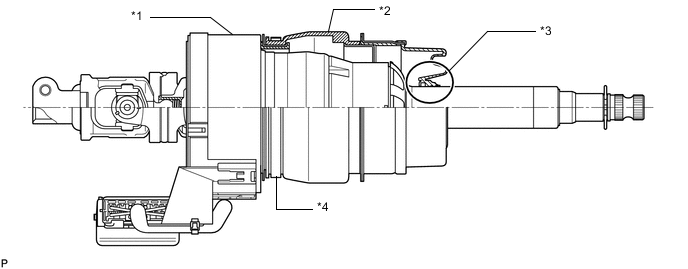
*1 Spiral Case *2 Boot *3 No. 2 Seal Lip *4 Actuator Clamp (Not tighten at first)
-
-
INSTALL STEERING ACTUATOR ASSEMBLY
-
Make sure that the power steering link assembly is centered.
-
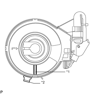
*1 White Line *2 Center Lock Pin Install the steering actuator assembly.
-
If installing a new steering actuator assembly:
Install the steering actuator assembly with the white line on the upper surface of the spiral case facing down.
Note
Do not pull out the center lock pin.
-
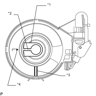
*1 Sliding Yoke *2 Slit *3 White Line *4 Alignment Mark If reinstalling the removed steering actuator assembly:
-
Slowly turn the spiral case clockwise until it locks.
-
Turn the spiral case two turns counterclockwise from the lock position.
-
Align the slit of the sliding yoke with the alignment mark (▲).
-
Install the steering actuator assembly with the white line on the upper surface of the spiral case facing down.
-
-
-
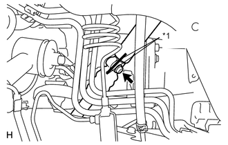
*1 Matchmark Align the matchmarks on the No. 2 steering intermediate shaft and steering actuator.
Tech Tips
Install the steering actuator from the inside of the vehicle.
Note
-
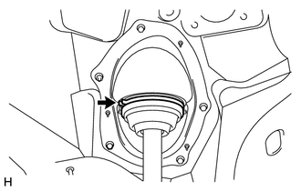
Do not fold back the boot part of the steering hole cover or turn it excessively. If it is turned excessively, return it to its original position.
-
Do not turn the actuator body and the spiral case.
-
-
Install the bolt.
- Torque:
- 35 N*m { 357 kgf*cm, 26 ft.*lbf }
-
Using needle nose pliers, lock the clamp to the steering column hole cover to install it.
Note
Be careful when performing the operation as the clamp may not lock if the claws of the clamp are deformed.
-
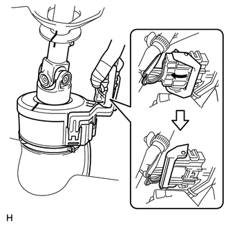
Move the lock in the direction of the arrow and connect the steering actuator connector.
Tech Tips
When a new actuator is installed, remove the center lock pin.
-
Connect the connector.
-
Install the front wheel LH side.
-
-
INSTALL STEERING COLUMN ASSEMBLY
-
PERFORM VARIABLE GEAR RATIO STEERING SYSTEM CALIBRATION