VARIABLE GEAR RATIO STEERING SYSTEM, Diagnostic DTC:C15A1/61, C15A2/62, C15A6/62
| DTC Code | DTC Name |
|---|---|
| C15A1/61 | Actuator Malfunction |
| C15A2/62 | Open in Motor Circuit |
| C15A6/62 | Actuator Motor Power Distribution Malfunction |
DESCRIPTION
If the VGRS ECU (steering control ECU) detects excessive current, it stores DTC C15A1/61, turns on the master warning light.
If the VGRS ECU (steering control ECU) detects excessive current flowing into the steering actuator assembly or an internal malfunction, it turns the master warning light on, and stores DTC C15A2/62.
If the VGRS ECU (steering control ECU) detects a malfunction in the motor drive circuit, it turns the master warning light on, and stores DTC C15A6/62.
| DTC No. | DTC Detection Condition | Trouble Area |
|---|---|---|
| C15A1/61 | Either condition is met:
|
|
| C15A2/62 | Either condition is met:
|
|
| C15A6/62 | Either condition is met:
|
|
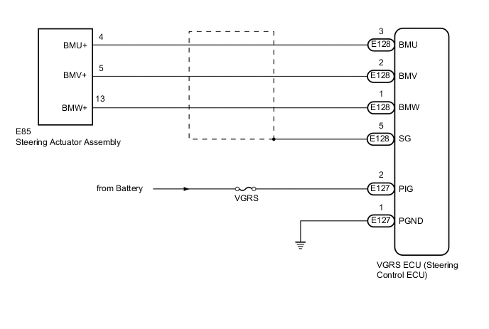
WIRING DIAGRAM
CAUTION / NOTICE / HINT
Note
-
When replacing the VGRS ECU (steering control ECU) or steering actuator assembly, perform actuator angle neutral point calibration and initialization after replacing parts Click here.
-
Inspect the fuses for circuits related to this system before performing the following inspection procedure.
Tech Tips
When DTC C15A2/62 is output, a short circuit inside the steering actuator assembly or inside the VGRS ECU (steering control ECU) is suspected.
PROCEDURE
-
CHECK HARNESS AND CONNECTOR (PIG, PGND TERMINAL)
-
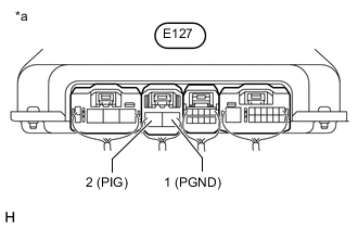
Text in Illustration *a Component with harness connected
(VGRS ECU [Steering Control ECU])
Turn the engine switch off.
-
Measure the resistance according to the value(s) in the table below.
Tech Tips
Perform the inspection from the rear of the connector with the connector connected to the VGRS ECU (steering control ECU).
Standard Resistance Tester Connection Condition Specified Condition E127-1(PGND) - Body ground Always Always -
Measure the voltage according to the value(s) in the table below.
Standard Voltage Tester Connection Condition Specified Condition E127-2(PIG) - E127-1(PGND) Always 11 to 14 V
NG 
REPAIR OR REPLACE HARNESS OR CONNECTOR
OK 
-
-
INSPECT STEERING ACTUATOR ASSEMBLY
-
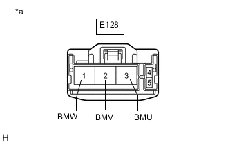
Text in Illustration *a Front view of wire harness connector
(to VGRS ECU [Steering Control ECU])
Disconnect the VGRS ECU (steering control ECU) connector.
-
Measure the resistance according to the value(s) in the table below.
Tech Tips
Measure the resistance of the steering actuator assembly at the connector of the VGRS ECU (steering control ECU).
Standard Resistance Tester Connection Condition Specified Condition E128-2 (BMV) - E128-3 (BMU) Always Below 1 Ω E128-2 (BMV) - E128-1 (BMW) Always Below 1 Ω E128-3 (BMU) - E128-1 (BMW) Always Below 1 Ω E128-1 (BMW) - Body ground Always 100 kΩ or higher E128-2 (BMV) - Body ground Always 100 kΩ or higher E128-3 (BMU) - Body ground Always 100 kΩ or higher Result Result Proceed to The resistance value deviates from the standard A The resistance value is within the standard B
B 
RECONFIRM DTC Click here
A
-
-
CHECK HARNESS AND CONNECTOR (VGRS ECU (STEERING CONTROL ECU) - STEERING ACTUATOR ASSEMBLY)
-
Turn the engine switch off.
-
Disconnect the E128 VGRS ECU (steering control ECU) connector.
-
Disconnect the E85 steering actuator assembly connector.
-
Measure the resistance according to the value(s) in the table below.
Standard Resistance Tester Connection Condition Specified Condition E128-2 (BMV) - E85-5 (BMV+) Always Below 1 Ω E128-3 (BMU) - E85-4 (BMU+) Always Below 1 Ω E128-1 (BMW) - E85-13 (BMW+) Always Below 1 Ω E128-2 (BMV) - E128-3 (BMU) Always 100 kΩ or higher E128-2 (BMV) - E128-1 (BMW) Always 100 kΩ or higher E128-3 (BMU) - E128-1 (BMW) Always 100 kΩ or higher E128-2 (BMV) or E85-5 (BMV+) - Body ground Always 100 kΩ or higher E128-3 (BMU) or E85-4 (BMU+) - Body ground Always 100 kΩ or higher E128-1 (BMW) or E85-13 (BMW+) - Body ground Always 100 kΩ or higher
OK
REPLACE STEERING ACTUATOR ASSEMBLY Click here
NG
REPAIR OR REPLACE HARNESS OR CONNECTOR
-
-
RECONFIRM DTC
-
Reconnect the VGRS ECU (steering control ECU) connector.
-
Clear the DTCs Click here.
-
Start the engine.
-
Check for DTCs Click here.
Result Result Proceed to DTCs C15A1/61, C15A2/62 and C15A6/62 is not output (for LHD) A DTCs C15A1/61, C15A2/62 and C15A6/62 is not output (for RHD) B DTCs C15A1/61, C15A2/62 and C15A6/62 is output C
A
REPLACE VGRS ECU (STEERING CONTROL ECU) Click here
B
REPLACE VGRS ECU (STEERING CONTROL ECU) Click here
C
REPLACE STEERING ACTUATOR ASSEMBLY Click here
-