ELECTRIC PARKING BRAKE SYSTEM Electric Parking Brake System AUTO Function Circuit
DESCRIPTION
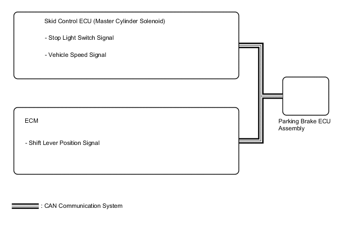
The parking brake ECU assembly receives shift position information from the ECM via CAN communication, and wheel speed signal and stop light switch signals from the skid control ECU (master cylinder solenoid).
The electric parking brake system AUTO function (shift-linked function) automatically releases the parking brake when the following conditions are met: 1) Engine switch is on (IG), 2) brake pedal is depressed, and 3) shift lever is moved out of P. When the shift lever is moved to P with these conditions met, the function automatically locks the parking brake.
The electric parking brake system AUTO (shift-linked function) automatically engages the parking brake when the shift level is moved to P and disengages the parking brake when the shift lever is moved out of P when the engine switch is on (IG) and the brake pedal is depressed.
WIRING DIAGRAM
CAUTION / NOTICE / HINT
Note
-
If the parking brake ECU assembly is replaced, perform the "Reset Memory" and "Acquire Tension Sensor Zero Point" procedures Click here.
-
Before disconnecting connectors or fuses, turn the engine switch off and wait 20 seconds or more.
-
Inspect the fuses for circuits related to this system before performing the following inspection procedure.
PROCEDURE
-
CHECK DTC (CAN COMMUNICATION SYSTEM)
-
Check for DTCs Click here.
Result Result Proceed to DTC is not output A DTC is output (for LHD) B DTC is output (for RHD) C
B 
GO TO CAN COMMUNICATION SYSTEM (HOW TO PROCEED WITH TROUBLESHOOTING) Click here
C
GO TO CAN COMMUNICATION SYSTEM (HOW TO PROCEED WITH TROUBLESHOOTING) Click here
A 
-
-
READ VALUE USING GTS (AUTO MODE)
-
Turn the engine switch off.
-
Connect the GTS to the DLC3.
-
Turn the engine switch on (IG) and the GTS on.
-
Enter the following menus: Chassis / Electric Parking Brake / Data List.
-
Check the values by referring to the table below.
Electric Parking Brake Tester Display Measurement Item/Range Switch Condition Normal Condition Auto Mode AUTO (shift-linked) mode permission display/
ON or OFF
Engine switch on (IG)
AUTO switch is pressed and held
ON: AUTO (shift-linked) mode
OFF: Manual mode
OK When switching the mode, check that the Data List display turns on and off. Tech Tips
For details regarding mode switching: Click here
Result Result Proceed to The Data List display does not turn on and off according to mode switching. A The Data List display turns on and off according to mode switching. B
B 
READ VALUE USING GTS (P/N/R/D POSITION) Click here
A
-
-
INSPECT ELECTRIC PARKING BRAKE SWITCH ASSEMBLY
-
Remove the electric parking brake switch assembly Click here.
-
Inspect the electric parking brake switch assembly Click here.
NG
REPLACE ELECTRIC PARKING BRAKE SWITCH ASSEMBLY
OK
-
-
CHECK HARNESS AND CONNECTOR (PARKING BRAKE ECU - ELECTRIC PARKING BRAKE SWITCH ASSEMBLY)
-
Disconnect the K53 parking brake ECU assembly connector.
-
Disconnect the V13 electric parking brake switch assembly connector.
-
Measure the resistance according to the value(s) in the table below.
Standard Resistance for LHD: Tester Connection Condition Specified Condition K53-12 (LCK1) - V13-8 (LOK1) Always Below 5 Ω K53-15 (LCK2) - V13-9 (LOK2) Always Below 5 Ω K53-12 (LCK1) or V13-8 (LOK1) - Body ground Always 10 kΩ or higher K53-15 (LCK2) or V13-9 (LOK2) - Body ground Always 10 kΩ or higher K53-16 (REL1) - V13-1 (RLS1) Always Below 5 Ω K53-13 (REL2) - V13-2 (REL1) Always Below 5 Ω K53-16 (REL1) or V13-1 (RLS1) - Body ground Always 10 kΩ or higher K53-13 (REL2) or V13-2 (REL1) - Body ground Always 10 kΩ or higher V13-14 (GND1) - Body ground Always Below 5 Ω for RHD: Tester Connection Condition Specified Condition K53-12 (LCK1) - V13-14 (LOK1) Always Below 5 Ω K53-15 (LCK2) - V13-13 (LOK2) Always Below 5 Ω K53-12 (LCK1) or V13-14 (LOK1) - Body ground Always 10 kΩ or higher K53-15 (LCK2) or V13-13 (LOK2) - Body ground Always 10 kΩ or higher K53-16 (REL1) - V13-7 (RLS1) Always Below 5 Ω K53-13 (REL2) - V13-6 (RLS2) Always Below 5 Ω K53-16 (REL1) or V13-7 (RLS1) - Body ground Always 10 kΩ or higher K53-13 (REL2) or V13-6 (RLS2) - Body ground Always 10 kΩ or higher V13-8 (GND1) - Body ground Always Below 5 Ω
NG
REPAIR OR REPLACE HARNESS OR CONNECTOR
OK
-
-
READ VALUE USING GTS (P/N/R/D POSITION)
-
Turn the engine switch off.
-
Connect the GTS to the DLC3.
-
Turn the engine switch on (IG) and the GTS on.
-
Enter the following menus: Chassis / Electric Parking Brake / Data List.
-
Check the values by referring to the table below.
Electric Parking Brake Tester Display Measurement Item/Range Condition Normal Condition P Position Shift lever position input information display/
ON or OFF
Engine switch on (IG)
Shift lever is in P
ON: Shift lever is in P
OFF: Shift lever not in P
N Position Shift lever position input information display/
ON or OFF
Engine switch on (IG)
Shift lever is in N
ON: Shift lever is in N
OFF: Shift lever not in N
R Position Shift lever position input information display/
ON or OFF
Engine switch on (IG)
Shift lever is in R
ON: Shift lever is in R
OFF: Shift lever not in R
D Position Shift lever position input information display/
ON or OFF
Engine switch on (IG)
Shift lever is in D
ON: Shift lever is in D
OFF: Shift lever not in D
OK On the GTS screen, item changes between ON and OFF according to shift lever operation. Result Result Proceed to OK A NG (for AE80F) B NG (for AB60F) C
B
GO TO AUTOMATIC TRANSMISSION SYSTEM (HOW TO PROCEED WITH TROUBLESHOOTING) Click here
C
GO TO AUTOMATIC TRANSMISSION SYSTEM (HOW TO PROCEED WITH TROUBLESHOOTING) Click here
A
-
-
READ VALUE USING GTS (STOP LIGHT SWITCH)
-
Turn the engine switch off.
-
Connect the GTS to the DLC3.
-
Turn the engine switch on (IG) and the GTS on.
-
Enter the following menus: Chassis / Electric Parking Brake / Data List.
-
Check the values by referring to the table below.
Electric Parking Brake Tester Display Measurement Item/Range Switch Condition Normal Condition Stop Light Switch Stop light switch input information display/
ON or OFF
Engine switch on (IG)
Stop light switch ON (brake pedal depressed)
ON: Stop light switch ON (brake pedal depressed)
OFF: Stop light switch OFF (brake pedal released)
OK On the GTS screen, item changes between ON and OFF according to switch operation.
OK
REPLACE PARKING BRAKE ECU ASSEMBLY Click here
NG
GO TO VEHICLE STABILITY CONTROL SYSTEM (HOW TO PROCEED WITH TROUBLESHOOTING) Click here
-