ELECTRIC PARKING BRAKE SYSTEM Electric Parking Brake does not Operate
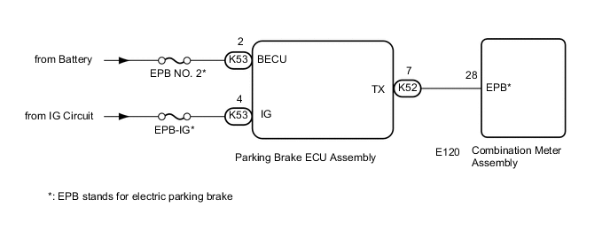
WIRING DIAGRAM
CAUTION / NOTICE / HINT
Note
-
If the parking brake ECU assembly is replaced, perform the "Reset Memory" and "Acquire Tension Sensor Zero Point" procedures Click here.
-
Before disconnecting connectors or fuses, turn the engine switch off and wait 20 seconds or more.
-
Inspect the fuses for circuits related to this system before performing the following inspection procedure.
Tech Tips
The condition may be that the electric parking brake is operating normally but the meter's parking brake indicator light (red) is malfunctioning.
PROCEDURE
-
VEHICLE OPERATION CHECK
-
Start the engine and move the shift lever to D. Then depress the brake pedal and pull the electric parking brake switch assembly to the lock side for 1 second. Check the parking brake indicator light (red) condition.
-
Release the brake pedal and check that the vehicle does not move.
-
Depress the brake pedal and push the electric parking brake switch assembly to the release side for 1 second. Check the parking brake indicator light (red) condition.
-
Release the brake pedal and check that the vehicle moves.
Result Result Proceed to Lock and release control is normal; parking brake indicator light (red) is off or is blinking A Lock and release control is malfunctioning; parking brake indicator light (red) is illuminated or off depending on switch operation B Lock and release control is malfunctioning; parking brake indicator light (red) is off or is blinking C
B 
READ VALUE USING GTS (Tension Sensor 1 Value, Tension Sensor 2 Value) Click here
C
CHECK HARNESS AND CONNECTOR (BATTERY - PARKING BRAKE ECU) Click here
A 
-
-
PERFORM ACTIVE TEST USING GTS (PKB LIGHT)
-
Turn the engine switch off.
-
Connect the GTS to the DLC3.
-
Turn the engine switch on (IG) and the GTS on.
-
Enter the following menus: Chassis / Electric Parking Brake / Active Test.
-
Check the condition of the parking brake indicator light (red) by operating the GTS.
Electric Parking Brake Tester Display Test Part Control Range Diagnostic Note PKB Light Parking brake indicator light (red) ON or OFF Vehicle speed is 0 km/h (0 mph) OK Indicator light turns on when operating the GTS.
OK 
REPLACE PARKING BRAKE ECU ASSEMBLY Click here
NG
-
-
CHECK HARNESS AND CONNECTOR (PARKING BRAKE ECU - COMBINATION METER)
-
Turn the engine switch off.
-
Disconnect the K52 parking brake ECU assembly connector.
-
Disconnect the E120 combination meter assembly connector.
-
Measure the resistance according to the value(s) in the table below.
Standard Resistance Tester Connection Condition Specified Condition K52-7 (TX) - E120-28 (EPB)* Always Below 1 Ω K52-7 (TX) or E120-28 (EPB)* - Body ground Always 10 kΩ or higher Tech Tips
*: EPB stands for electric parking brake
OK
GO TO METER / GAUGE SYSTEM (HOW TO PROCEED WITH TROUBLESHOOTING) Click here
NG
REPAIR OR REPLACE HARNESS OR CONNECTOR
-
-
CHECK HARNESS AND CONNECTOR (BATTERY - PARKING BRAKE ECU)
-
Turn the engine switch off.
-
Disconnect the parking brake ECU assembly connector.
-
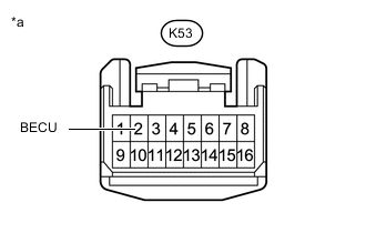
Text in Illustration *a Front view of wire harness connector
(to Parking Brake ECU Assembly)
Measure the voltage according to the value(s) in the table below.
Standard Voltage Tester Connection Condition Specified Condition K53-2 (BECU) - Body ground Always 11 to 14 V
NG
REPAIR OR REPLACE HARNESS OR CONNECTOR
OK
-
-
CHECK HARNESS AND CONNECTOR (IG CIRCUIT - PARKING BRAKE ECU)
-
Turn the engine switch off.
-
Disconnect the parking brake ECU assembly connector.
-
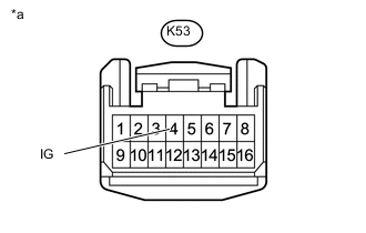
Text in Illustration *a Front view of wire harness connector
(to Parking Brake ECU Assembly)
Measure the voltage according to the value(s) in the table below.
Standard Voltage Tester Connection Condition Specified Condition K53-4 (IG) - Body ground Engine switch on (IG) 11 to 14 V
OK
REPLACE PARKING BRAKE ECU ASSEMBLY Click here
NG
REPAIR OR REPLACE HARNESS OR CONNECTOR
-
-
READ VALUE USING GTS (Tension Sensor 1 Value, Tension Sensor 2 Value)
-
Turn the engine switch off.
-
Connect the GTS to the DLC3.
-
Turn the engine switch on (IG) and the GTS on.
-
Enter the following menus: Chassis / Electric Parking Brake / Active Test.
-
Check the condition of the parking brake indicator light (red) by operating the GTS.
Electric Parking Brake Tester Display Measurement Item/Range Normal Condition Diagnostic Note Tension Sensor 1 Value Tension sensor 1 value input information is displayed/
Min.: 0.000 V
Max.: 5.000 V
0.5 to 4.5 V - Tension Sensor 2 Value Tension sensor 2 value input information is displayed/
Min.: 0.000 V
Max.: 5.000 V
0.5 to 4.5 V - OK Display changes according to operation of the electric parking brake switch assembly.
OK
CHECK PARKING BRAKE ASSEMBLY Click here
NG
-
-
INSPECT PARKING BRAKE CABLE
-
Check that the parking brake cable is not stuck Click here.
OK
CHECK PARKING BRAKE ASSEMBLY Click here
NG
REPAIR OR REPLACE PARKING BRAKE CABLE Click here
-