ELECTRIC PARKING BRAKE SYSTEM, Diagnostic DTC:C13A4/32, C13AC/34
| DTC Code | DTC Name |
|---|---|
| C13A4/32 | Open or Short in Release Switch Circuit |
| C13AC/34 | Release Switch Circuit |
DESCRIPTION
When the electric parking brake switch assembly is pushed to the release side, a release request signal is output to the parking brake ECU assembly.
| DTC Code | Detection Condition | Trouble Area | Note |
|---|---|---|---|
| C13A4/32 | All of following conditions are met:
|
|
An electric parking brake system malfunction is displayed on the multi-information display. |
| C13AC/34 | Both of following conditions are met:
|
|
An electric parking brake system malfunction is displayed on the multi-information display. |
Tech Tips
*: When battery voltage is 11 V
WIRING DIAGRAM
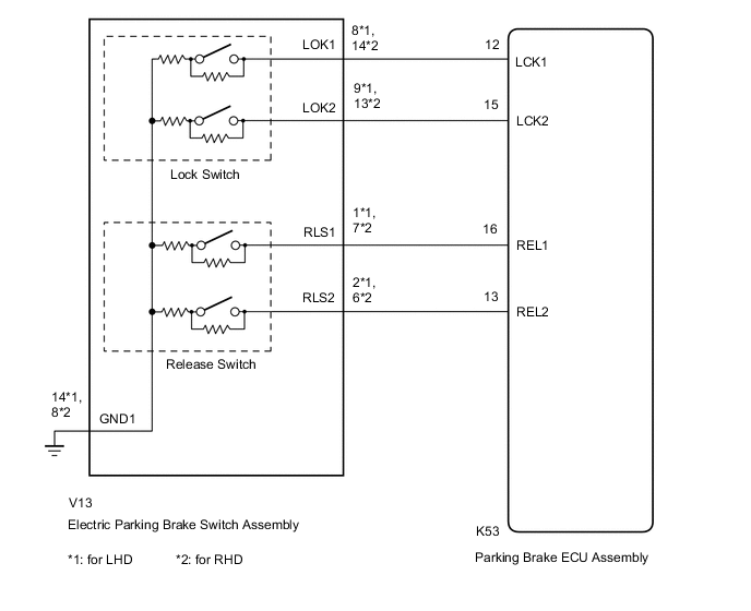
CAUTION / NOTICE / HINT
Note
-
If the parking brake ECU assembly is replaced, perform the "Reset Memory" and "Acquire Tension Sensor Zero Point" procedures Click here.
-
Before disconnecting connectors or fuses, turn the engine switch off and wait 20 seconds or more.
-
When the electric parking brake switch assembly is pushed and held for 1 second or more without being pushed fully to the release side, one of the 2 linked contacts may turn on while the other one turns off causing this DTC to be stored (system is not malfunctioning).
PROCEDURE
-
INSPECT ELECTRIC PARKING BRAKE SWITCH ASSEMBLY
-
Remove the electric parking brake switch assembly Click here.
-
Inspect the electric parking brake switch assembly Click here.
NG 
REPLACE ELECTRIC PARKING BRAKE SWITCH ASSEMBLY Click here
OK 
-
-
CHECK HARNESS AND CONNECTOR (PARKING BRAKE ECU - ELECTRIC PARKING BRAKE SWITCH)
-
Turn the engine switch off.
-
Disconnect the K53 parking brake ECU assembly connector.
-
Disconnect the V13 electric parking brake switch assembly connector.
-
Measure the resistance according to the value(s) in the table below.
Standard Resistance for LHD: Tester Connection Condition Specified Condition K53-16 (REL1) - V13-1 (RLS1) Always Below 5 Ω K53-13 (REL2) - V13-2 (RLS2) Always Below 5 Ω K53-16 (REL1) or V13-1 (RLS1) - Body ground Always 10 kΩ or higher K53-13 (REL2) or V13-2 (RLS2) - Body ground Always 10 kΩ or higher V13-14 (GND1) - Body ground Always Below 5 Ω for RHD: Tester Connection Condition Specified Condition K53-16 (REL1) - V13-7 (RLS1) Always Below 5 Ω K53-13 (REL2) - V13-6 (RLS2) Always Below 5 Ω K53-16 (REL1) or V13-7 (RLS1) - Body ground Always 10 kΩ or higher K53-13 (REL2) or V13-6 (RLS2) - Body ground Always 10 kΩ or higher V13-8 (GND1) - Body ground Always Below 5 Ω
NG
REPAIR OR REPLACE HARNESS OR CONNECTOR
OK
-
-
CLEAR DTC
-
Turn the engine switch off.
-
Securely install the parking brake ECU assembly connectors and electric parking brake switch assembly.
-
Connect the GTS to the DLC3.
-
Turn the engine switch on (IG) and the GTS on.
-
Clear the DTC Click here.
NEXT
-
-
CHECK FOR DTC
-
Turn the engine switch off.
-
Connect the GTS to the DLC3.
-
Turn the engine switch on (IG) and the GTS on.
-
Perform a release operation with the electric parking brake switch assembly.
Tech Tips
When the electric parking brake switch assembly is pushed and held for 1 second or more without being pushed fully to the release side, one of the 2 linked contacts may turn on while the other one turns off causing this DTC to be stored (system is not malfunctioning).
-
Check for DTC Click here.
Result Result Proceed to DTC is output A DTC is not output B
A
REPLACE PARKING BRAKE ECU ASSEMBLY Click here
B
USE SIMULATION METHOD TO CHECK Click here
-