ELECTRIC PARKING BRAKE SYSTEM TERMINALS OF ECU
-
CHECK PARKING BRAKE ECU ASSEMBLY
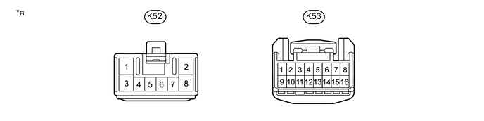
Text in Illustration *a Front view of wire harness connector
(to Parking Brake ECU Assembly)
- -
-
Disconnect the parking brake ECU assembly connectors.
-
Measure the voltage and resistance according to the values in the table below.
Terminal No. (Symbol) Wiring Color Terminal Description Condition Specified Condition K52-3 (GND1) - Body ground W-B Ground Always Below 1 Ω K52-8 (+B) - Body ground R Electric parking brake motor power supply Engine switch off 11 to 14 V K53-1 (CA2L) - K53-9 (CA2H) B - LG CAN communication line Engine switch off 54 to 69 Ω K53-2 (BECU) - Body ground L Parking brake ECU power supply Engine switch off 11 to 14 V K53-4 (IG) - Body ground B IG power supply Engine switch on (IG) 11 to 14 V -
Connect the parking brake ECU assembly connectors.

Text in Illustration *a Component with harness connected
(Parking Brake ECU Assembly)
- - -
Measure the voltage and resistance according to the values in the table below.
Terminal No. (Symbol) Wiring Color Terminal Description Condition Specified Condition K52-1 (M-) - Body ground L Electric parking brake motor Engine switch on (IG)
Electric parking brake not operating
4.5 to 6.8 V K52-2 (M+) - Body ground R Electric parking brake motor Engine switch on (IG)
Electric parking brake not operating
4.5 to 6.8 V K52-6 (POL) - Body ground W Electric parking brake switch indicator light Engine switch on (IG)
Electric parking brake switch indicator light off
11 to 14 V K52-7 (TX) - Body ground V Combination meter communication signal 20 seconds after engine switch turned off 9 to 14 V K53-6 (TSN2) - Body ground W Tension sensor 2 Engine switch on (IG) 0.5 to 4.5 V K53-7 (VT) - Body ground R Tension sensor power supply Engine switch on (IG) 4.75 to 5.25 V K53-8 (TSEN) - Body ground B Tension sensor 1 Engine switch on (IG) 0.5 to 4.5 V K53-10 (SG) - Body ground - - Always Below 1 Ω K53-12 (LCK1) - Body ground B Electric parking brake switch assembly lock 1 Engine switch on (IG)
Electric parking brake switch assembly off (released)
1.8 to 3.3 V Engine switch on (IG)
Electric parking brake switch assembly pulled and held to lock side
2.2 to 3.7 V K53-13 (REL2) - Body ground GR Electric parking brake switch assembly release 2 Engine switch on (IG)
Electric parking brake switch assembly off (released)
6.5 to 10 V Engine switch on (IG)
Electric parking brake switch assembly pushed and held to release side
2.8 to 5 V K53-14 (TGND) - Body ground G Tension sensor ground Always Below 1 Ω K53-15 (LCK2) - Body ground R Electric parking brake switch assembly lock 2 Engine switch on (IG)
Electric parking brake switch assembly off (released)
6.5 to 10 V Engine switch on (IG)
Electric parking brake switch assembly pulled and held to lock side
2.8 to 5 V K53-16 (REL1) - Body ground G Electric parking brake switch assembly release 1 Engine switch on (IG)
Electric parking brake switch assembly off (released)
6.5 to 10 V Engine switch on (IG)
Electric parking brake switch assembly pushed and held to release side
2.8 to 5 V
-