VEHICLE STABILITY CONTROL SYSTEM TRC OFF Indicator Light Remains ON
DESCRIPTION
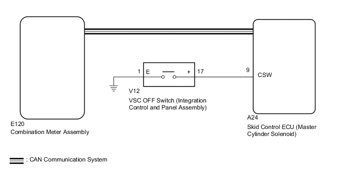
The TRC OFF indicator light comes on when the VSC OFF switch (integration control and panel assembly) is operated.
WIRING DIAGRAM
CAUTION / NOTICE / HINT
Note
After replacing the master cylinder solenoid, perform zero point calibration and store the system information Click here.
PROCEDURE
-
INSPECT IF SKID CONTROL ECU CONNECTOR IS SECURELY CONNECTED
-
Check the skid control ECU (master cylinder solenoid) connector connection.
OK The connector is securely connected.
NG 
CONNECT CONNECTOR TO ECU CORRECTLY
OK 
-
-
CHECK CAN COMMUNICATION LINE
-
Turn the engine switch off.
-
Connect the GTS to the DLC3.
-
Turn the engine switch on (IG) and the GTS on.
-
Select "CAN Bus Check" from the System Selection Menu screen, and follow the prompts on the screen to inspect the CAN Bus.
OK "CAN Bus Check" indicates no malfunctions in CAN communication. Result Result Proceed to OK A NG (for LHD) B NG (for RHD) C
B
GO TO CAN COMMUNICATION SYSTEM (HOW TO PROCEED WITH TROUBLESHOOTING) Click here
C
GO TO CAN COMMUNICATION SYSTEM (HOW TO PROCEED WITH TROUBLESHOOTING) Click here
A
-
-
CHECK DTC (CAN COMMUNICATION SYSTEM)
-
Turn the engine switch off.
-
Connect the GTS to the DLC3.
-
Turn the engine switch on (IG) and the GTS on.
-
Check for DTCs (for LHD: See page , for RHD: Click here.
Result Result Proceed to CAN system DTC is not output A CAN system DTC is output (for LHD) B CAN system DTC is output (for RHD) C
B
GO TO CAN COMMUNICATION SYSTEM (HOW TO PROCEED WITH TROUBLESHOOTING) Click here
C
GO TO CAN COMMUNICATION SYSTEM (HOW TO PROCEED WITH TROUBLESHOOTING) Click here
A
-
-
READ VALUE USING GTS (TRC/VSC OFF MODE)
-
Turn the engine switch off.
-
Connect the GTS to the DLC3.
-
Turn the engine switch on (IG).
-
Turn the GTS on.
-
Enter the following menus: Chassis / ABS/VSC/TRC / Data List.
ABS/VSC/TRC Tester Display Measurement Item/Range Normal Condition Diagnostic Note TRC/VSC Off Mode TRC/VSC off mode/ Normal, TRC OFF, Unknown or VSC OFF Normal: Normal mode
TRC OFF: TRC OFF mode
VSC OFF: VSC OFF mode
- -
Check that the mode display changes according to VSC OFF switch operation.
OK Display changes according to switch operation.
OK
GO TO METER / GAUGE SYSTEM (HOW TO PROCEED WITH TROUBLESHOOTING) Click here
NG
-
-
INSPECT INTEGRATION CONTROL AND PANEL ASSEMBLY
-
Remove the VSC OFF switch (integration control and panel assembly) Click here.
-
Inspect the VSC OFF switch (integration control and panel assembly) Click here.
NG
REPLACE COMBINATION SWITCH ASSEMBLY Click here
OK
-
-
CHECK HARNESS AND CONNECTOR (SKID CONTROL ECU - INTEGRATION CONTROL AND PANEL ASSEMBLY)
-
Turn the engine switch off.
-
Disconnect the A24 skid control ECU (master cylinder solenoid) connector.
-
Disconnect the V12 VSC OFF switch (integration control and panel assembly) connector.
-
Measure the resistance according to the value(s) in the table below.
Standard Resistance Tester Connection Condition Specified Condition A24-9 (CSW) - V12-17 (+) Always Below 1 Ω A24-9 (CSW) - Body ground Always 10 kΩ or higher V12-17 (+) - Body ground Always Below 1 Ω Result Result Proceed to NG A OK (for LHD) B OK (for RHD) C
A
REPAIR OR REPLACE HARNESS OR CONNECTOR
B
REPLACE MASTER CYLINDER SOLENOID Click here
C
REPLACE MASTER CYLINDER SOLENOID Click here
-