VEHICLE STABILITY CONTROL SYSTEM, Diagnostic DTC:C1251
| DTC Code | DTC Name |
|---|---|
| C1251 | Open in Pump Motor Circuit |
DESCRIPTION
The motor relay (semiconductor relay) is built into the master cylinder solenoid and drives the pump motor based on a signal from the skid control ECU (master cylinder solenoid).
| DTC Code | DTC Detection Condition | Trouble Area |
|---|---|---|
| C1251 | There is an open in the motor system circuit (motor input circuit). |
|
WIRING DIAGRAM
Refer to DTC C1253 Click here.
CAUTION / NOTICE / HINT
Note
-
After replacing the master cylinder solenoid, perform zero point calibration and store the system information Click here.
-
Inspect the fuses for circuits related to this system before performing the following inspection procedure.
Tech Tips
Remove the hydraulic brake booster assembly before the inspection (for LHD: See page , for RHD: Click here.
PROCEDURE
-
CHECK CONNECTION OF PUMP MOTOR WIRE HARNESS
-
Remove the hydraulic brake booster assembly (for LHD: See page , for RHD: Click here.
-
Check the tightening torque of the 2 screws which secure the wire harness connecting the master cylinder solenoid and brake booster with accumulator pump assembly (for LHD: See page , for RHD: Click here.
OK The harness is tightened to the specified torque.
NG 
RETIGHTEN SCREWS
OK 
-
-
CHECK HARNESS AND CONNECTOR (+BM1/+BM2 TERMINAL)
-
Turn the engine switch off.
-
Disconnect the skid control ECU (master cylinder solenoid) connectors.
-
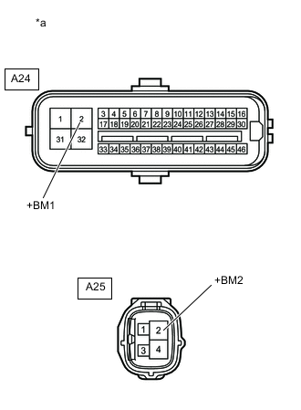
Text in Illustration *a Front view of wire harness connector
(to Skid Control ECU [Master Cylinder Solenoid])
Measure the voltage according to the value(s) in the table below.
Standard Voltage Tester Connection Condition Specified Condition A24-2 (+BM1) - Body ground Always 11 to 14 V A25-2 (+BM2) - Body ground Always 11 to 14 V
NG
REPAIR OR REPLACE HARNESS OR CONNECTOR
OK
-
-
CHECK HARNESS AND CONNECTOR (GND1, GND2 AND GND3 TERMINAL)
-
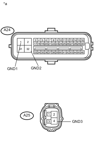
Text in Illustration *a Front view of wire harness connector
(to Skid Control ECU [Master Cylinder Solenoid])
Turn the engine switch off.
-
Disconnect the skid control ECU (master cylinder solenoid) connectors.
-
Measure the resistance according to the value(s) in the table below.
Standard Resistance Tester Connection Condition Specified Condition A24-1 (GND1) - Body ground Always Below 1 Ω A24-32 (GND2) - Body ground Always Below 1 Ω A25-4 (GND3) - Body ground Always Below 1 Ω
NG
REPAIR OR REPLACE HARNESS OR CONNECTOR
OK
-
-
CHECK RESISTANCE OF PUMP MOTOR WIRE HARNESS
-
Using a screwdriver, remove the 2 screws and pull out the wire harness from the master cylinder solenoid.
-
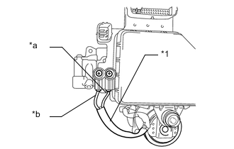
Text in Illustration *1 Pump motor wire harness *a Red wire *b Black wire Measure the resistance according to the value(s) in the table below.
Standard Resistance Tester Connection Condition Specified Condition Red wire terminal - Black wire terminal Always Below 2 Ω Tech Tips
-
for LHD Click here
-
for RHD Click here
Refer to the brake booster with accumulator pump assembly installation procedures:
-
NG
REPLACE BRAKE BOOSTER WITH ACCUMULATOR PUMP ASSEMBLY
OK
-
-
RECONFIRM DTC
-
Reassemble the hydraulic brake booster assembly (for LHD: See page , for RHD: Click here.
-
Install the hydraulic brake booster assembly (for LHD: See page , for RHD: Click here.
-
Clear the DTCs Click here.
-
Turn the engine switch off.
-
Check if the same DTC is output Click here.
Result Result Proceed to DTC is not output A DTC is output (for LHD) B DTC is output (for RHD) C
A
CHECK FOR INTERMITTENT PROBLEMS Click here
B
REPLACE MASTER CYLINDER SOLENOID Click here
C
REPLACE MASTER CYLINDER SOLENOID Click here
-