ACTIVE HEIGHT CONTROL SUSPENSION, Diagnostic DTC:C1718
| DTC Code | DTC Name |
|---|---|
| C1718 | Pressure Sensor Circuit Malfunction |
DESCRIPTION
This circuit is used for sending the data to detect the pressure output from the pump. The abnormality of the fluid pressure is judged by the ECU.
| DTC Code | Detecting Condition | Trouble Area |
|---|---|---|
| C1718 | When one of the following conditions is met:
|
|
WIRING DIAGRAM
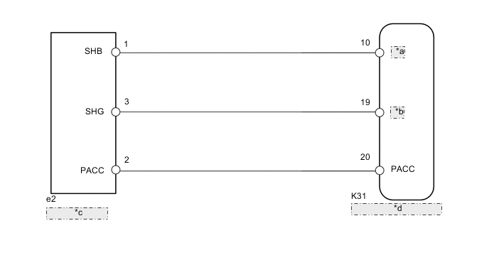
| *a | SPB |
| *b | SPG |
| *c | Pressure Sensor |
| *d | Suspension Control ECU |
CAUTION / NOTICE / HINT
Note
-
Before performing troubleshooting, inspect the connectors of related circuits.
-
If the suspension control ECU or height control sensor is replaced, the vehicle height offset calibration must be performed Click here.
PROCEDURE
-
CHECK HARNESS AND CONNECTOR (PRESSURE SENSOR - SUSPENSION CONTROL ECU)
Note
When inspecting the wire harness between the suspension control ECU and pressure sensor, it is difficult to determine the malfunctioning area if there is a sensor power supply malfunction. Therefore, disconnect the connectors for the pressure sensor, the acceleration sensors (front RH, front LH) and fluid temperature sensor on the ECU side.
-
Disconnect the e2 pressure sensor connector.
-
Disconnect the K30 and K31 ECU connectors.
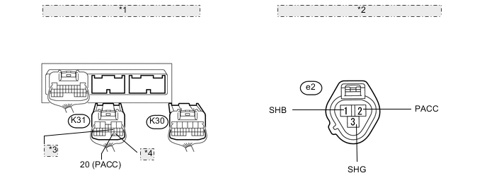
*1 Rear view of wire harness connector: (to Suspension Control ECU) *2 Front view of wire harness connector: (to Pressure Sensor) *3 10 (SPB) *4 19 (SPG) -
Measure the resistance according to the value(s) in the table below.
Standard Resistance Tester Connection Condition Specified Condition K31-10 (SPB) - e2-1 (SHB) Always Below 1 Ω K31-19 (SPG) - e2-3 (SHG) Always Below 1 Ω K31-20 (PACC) - e2-2 (PACC) Always Below 1 Ω K31-10 (SPB) - Body ground Always 10 kΩ or higher K31-19 (SPG) - Body ground Always 10 kΩ or higher K31-20 (PACC) - Body ground Always 10 kΩ or higher
NG 
REPAIR OR REPLACE HARNESS OR CONNECTOR
OK 
-
-
CHECK SUSPENSION CONTROL ECU
-
Connect the K30 and K31 suspension control ECU connectors.
-
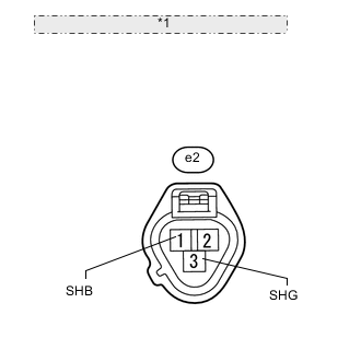
*1 Front view of wire harness connector: (to Pressure Sensor) Disconnect the e2 pressure sensor connector.
-
Measure the voltage according to the value(s) in the table below.
Standard Voltage Tester Connection Switch Condition Specified Condition e2-1 (SHB) - e2-3 (SHG) Engine switch on (IG) 4.75 to 5.25 V
NG
REPLACE SUSPENSION CONTROL ECU Click here
OK
-
-
CHECK PRESSURE SENSOR
-
Connect the K30 and K31 suspension control ECU connectors.
-
Connect the e2 pressure sensor connector.
-
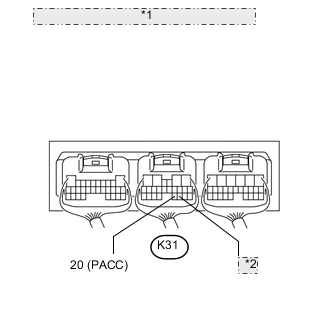
*1 Component with harness connected: (Suspension Control ECU) *2 19 (SPG) Start the engine and push the up button of the height control switch to activate height control.
-
Measure the voltage according to the value(s) in the table below.
Standard Voltage Tester Connection Condition Specified Condition K31-20 (PACC) - K31-19 (SPG) While height control is operating. 1.48 to 2.54 V
OK
REPLACE SUSPENSION CONTROL ECU Click here
NG
REPLACE HEIGHT CONTROL PUMP AND MOTOR
-