ACTIVE HEIGHT CONTROL SUSPENSION, Diagnostic DTC:C1731, C1732, C1733, C1734
| DTC Code | DTC Name |
|---|---|
| C1731 | Front Damping Force Control Actuator RH Circuit Malfunction |
| C1732 | Front Damping Force Control Actuator LH Circuit Malfunction |
| C1733 | Rear Damping Force Control Actuator RH Circuit Malfunction |
| C1734 | Rear Damping Force Control Actuator LH Circuit Malfunction |
DESCRIPTION
The ECU sends a signal to the damping force control actuator to drive the rotary valve of the shock absorber changing the shock absorber damping force.
The actuator is driven electromagnetically by a step motor so that it can accurately follow the driving conditions that change frequently.
| DTC Code | Detection Condition | Trouble Area |
|---|---|---|
| C1731 | When either of the following is detected:
|
|
| C1732 | When either of the following is detected:
|
|
| C1733 | When either of the following is detected:
|
|
| C1734 | When either of the following is detected:
|
|
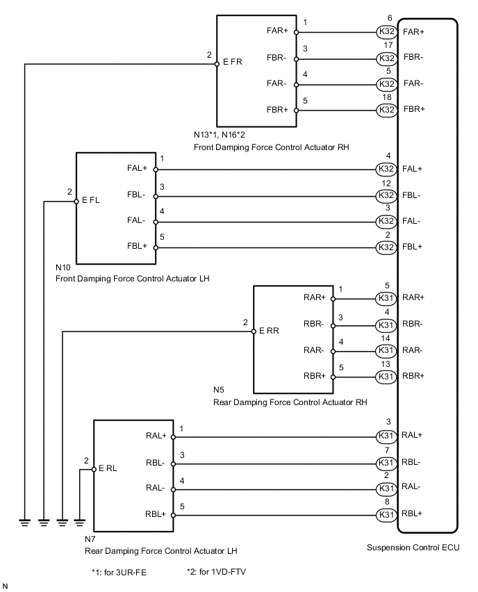
WIRING DIAGRAM
CAUTION / NOTICE / HINT
Note
-
Before performing troubleshooting, inspect the connectors of related circuits.
-
If the suspension control ECU or height control sensor is replaced, the vehicle height offset calibration must be performed Click here.
PROCEDURE
-
PERFORM ACTIVE TEST USING GTS (DAMPER STEP)
-
Turn the engine switch off.
-
Connect the GTS to the DLC3.
-
Start the engine and turn the GTS on.
-
Enter the following menus: Chassis / AHC / Active Test.
-
Check if the damping force control actuator operates in accordance with the Active Test.
AHC Tester Display Test Part Control Range Diagnostic Note Damper Step FR Changes front damper RH step min.: 1 step
max.: 16 step
The Damper Step item of the Data List changes to the step selected in the Active Test. Damper Step FL Changes front damper LH step min.: 1 step
max.: 16 step
The Damper Step item of the Data List changes to the step selected in the Active Test. Damper Step RR Changes rear damper RH step min.: 1 step
max.: 16 step
The Damper Step item of the Data List changes to the step selected in the Active Test. Damper Step RL Changes rear damper LH step min.: 1 step
max.: 16 step
The Damper Step item of the Data List changes to the step selected in the Active Test. OK The damping force control actuator operates.
NG 
CHECK HARNESS AND CONNECTOR (DAMPING FORCE CONTROL ACTUATOR - SUSPENSION CONTROL ECU) Click here
OK 
-
-
RECONFIRM DTC OUTPUT
-
Clear the DTCs Click here.
-
Perform a road test.
-
Check for DTCs.
Result Result Proceed to DTC is output A DTC is not output B
B 
USE SIMULATION METHOD TO CHECK Click here
A
-
-
CHECK HARNESS AND CONNECTOR (DAMPING FORCE CONTROL ACTUATOR - SUSPENSION CONTROL ECU)
-
Check the front side damping force control actuator.
-
for 3UR-FE:
Disconnect the N13 and/or N10 actuator connector.
for 1VD-FTV:
Disconnect the N16 and/or N10 actuator connector.
-
Disconnect the K32 ECU connector.
-
Measure the resistance according to the value(s) in the table below.
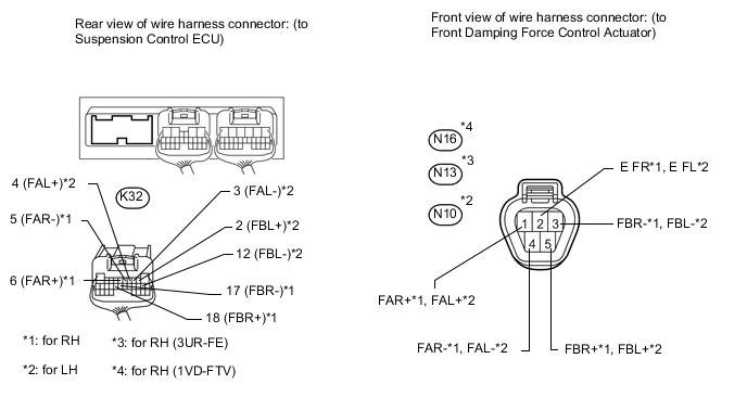
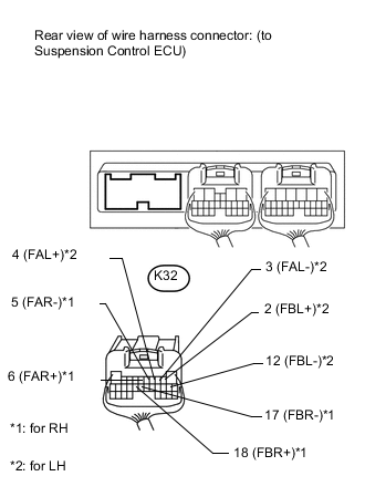
Standard Resistance for RH (C1731) Tester Connection Condition Specified Condition K32-5 (FAR-) - N13-4 (FAR-)*1
K32-5 (FAR-) - N16-4 (FAR-)*2
Always Below 1 Ω K32-5 (FAR-) - Body ground Always 10 kΩ or higher K32-6 (FAR+) - N13-1 (FAR+)*1
K32-6 (FAR+) - N16-1 (FAR+)*2
Always Below 1 Ω K32-6 (FAR+) - Body ground Always 10 kΩ or higher K32-17 (FBR-) - N13-3 (FBR-)*1
K32-17 (FBR-) - N16-3 (FBR-)*2
Always Below 1 Ω K32-17 (FBR-) - Body ground Always 10 kΩ or higher K32-18 (FBR+) - N13-5 (FBR+)*1
K32-18 (FBR+) - N16-5 (FBR+)*2
Always Below 1 Ω K32-18 (FBR+) - Body ground Always 10 kΩ or higher N13-2 (E FR) - Body ground Always Below 1 Ω for LH (C1732) Tester Connection Condition Specified Condition K32-2 (FBL+) - N10-5 (FBL+) Always Below 1 Ω K32-2 (FBL+) - Body ground Always 10 kΩ or higher K32-3 (FAL-) - N10-4 (FAL-) Always Below 1 Ω K32-3 (FAL-) - Body ground Always 10 kΩ or higher K32-4 (FAL+) - N10-1 (FAL+) Always Below 1 Ω K32-4 (FAL+) - Body ground Always 10 kΩ or higher K32-12 (FBL-) - N10-3 (FBL-) Always Below 1 Ω K32-12 (FBL-) - Body ground Always 10 kΩ or higher N10-2 (E FL) - Body ground Always Below 1 Ω
-
*1: for 3UR-FE
-
*2: for 1VD-FTV
-
-
-
Check the rear side damping force control actuator.
-
Disconnect the N5 and/or N7 actuator connector.
-
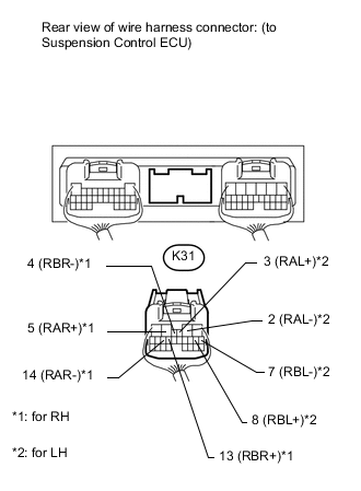
Disconnect the K31 ECU connector.
-
Measure the resistance according to the value(s) in the table below.
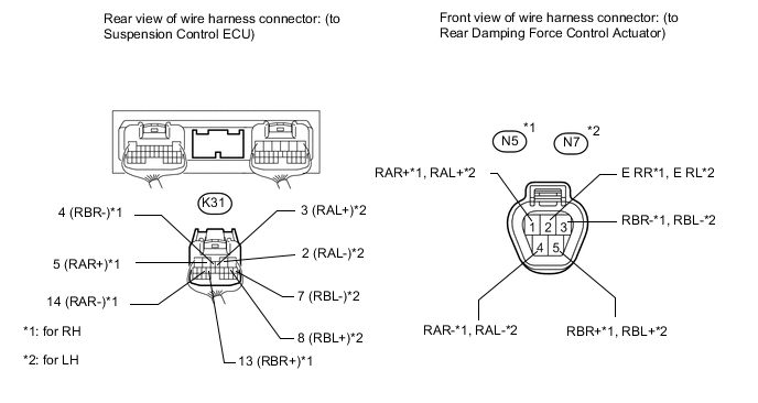
Standard Resistance for RH (C1733) Tester Connection Condition Specified Condition K31-4 (RBR-) - N5-3 (RBR-) Always Below 1 Ω K31-4 (RBR-) - Body ground Always 10 kΩ or higher K31-5 (RAR+) - N5-1 (RAR+) Always Below 1 Ω K31-5 (RAR+) - Body ground Always 10 kΩ or higher K31-13 (RBR+) - N5-5 (RBR+) Always Below 1 Ω K31-13 (RBR+) - Body ground Always 10 kΩ or higher K31-14 (RAR-) - N5-4 (RAR-) Always Below 1 Ω K31-14 (RAR-) - Body ground Always 10 kΩ or higher N5-2 (E RR) - Body ground Always Below 1 Ω for LH (C1734) Tester Connection Condition Specified Condition K31-2 (RAL-) - N7-4 (RAL-) Always Below 1 Ω K31-2 (RAL-) - Body ground Always 10 kΩ or higher K31-3 (RAL+) - N7-1 (RAL+) Always Below 1 Ω K31-3 (RAL+) - Body ground Always 10 kΩ or higher K31-7 (RBL-) - N7-3 (RBL-) Always Below 1 Ω K31-7 (RBL-) - Body ground Always 10 kΩ or higher K31-8 (RBL+) - N7-5 (RBL+) Always Below 1 Ω K31-8 (RBL+) - Body ground Always 10 kΩ or higher N7-2 (E RL) - Body ground Always Below 1 Ω
-
NG
REPAIR OR REPLACE HARNESS OR CONNECTOR
OK
-
-
INSPECT DAMPING FORCE CONTROL ACTUATOR
-
Check the front side damping force control actuator.
-
for 3UR-FE:
Connect the N13 and/or N10 front absorber control actuator connector.
for 1VD-FTV:
Connect the N16 and/or N10 front absorber control actuator connector.
-
Disconnect the K32 ECU connector.
-
Measure the resistance according to the value(s) in the table below.
Standard Resistance for RH (C1731) Tester Connection Condition Specified Condition K32-5 (FAR-) - Body ground Always 12.0 to 13.6 Ω K32-6 (FAR+) - Body ground Always 12.0 to 13.6 Ω K32-17 (FBR-) - Body ground Always 12.0 to 13.6 Ω K32-18 (FBR+) - Body ground Always 12.0 to 13.6 Ω for LH (C1732) Tester Connection Condition Specified Condition K32-2 (FBL+) - Body ground Always 12.0 to 13.6 Ω K32-3 (FAL-) - Body ground Always 12.0 to 13.6 Ω K32-4 (FAL+) - Body ground Always 12.0 to 13.6 Ω K32-12 (FBL-) - Body ground Always 12.0 to 13.6 Ω
-
-
Check the rear side damping force control actuator.
-
Connect the N5 and/or N7 rear absorber control actuator connector.
-
Disconnect the K31 ECU connector.
-
Measure the resistance according to the value(s) in the table below.
Standard Resistance for RH (C1733) Tester Connection Condition Specified Condition K31-4 (RBR-) - Body ground Always 12.0 to 13.6 Ω K31-5 (RAR+) - Body ground Always 12.0 to 13.6 Ω K31-13 (RBR+) - Body ground Always 12.0 to 13.6 Ω K31-14 (RAR-) - Body ground Always 12.0 to 13.6 Ω for LH (C1734) Tester Connection Condition Specified Condition K31-2 (RAL-) - Body ground Always 12.0 to 13.6 Ω K31-3 (RAL+) - Body ground Always 12.0 to 13.6 Ω K31-7 (RBL-) - Body ground Always 12.0 to 13.6 Ω K31-8 (RBL+) - Body ground Always 12.0 to 13.6 Ω
Result Result Proceed to OK A Front damping force control actuator RH malfunction B Front damping force control actuator LH malfunction C Rear damping force control actuator RH malfunction D Rear damping force control actuator LH malfunction E -
A
REPLACE SUSPENSION CONTROL ECU Click here
B
REPLACE FRONT SHOCK ABSORBER CONTROL VALVE RH Click here
C
REPLACE FRONT SHOCK ABSORBER CONTROL VALVE LH Click here
D
REPLACE REAR SHOCK ABSORBER CONTROL VALVE RH Click here
E
REPLACE REAR SHOCK ABSORBER CONTROL VALVE LH Click here
-