ACTIVE HEIGHT CONTROL SUSPENSION, Diagnostic DTC:C1736, C1737
| DTC Code | DTC Name |
|---|---|
| C1736 | Front Suspension Control Valve RH Malfunction |
| C1737 | Front Suspension Control Valve LH Malfunction |
DESCRIPTION
In order to decrease roll angle/pitch angle, the suspension control ECU turns the spring rate switching valve in the front suspension control valve off/on to change the fluid lines when the acceleration sensor or yaw rate sensor signal is input into the suspension control ECU. Normally, the spring rate switching valve is open.
| DTC Code | Detection Condition | Trouble area |
|---|---|---|
| C1736 | When either of the following is detected:
|
|
| C1737 | When either of the following is detected:
|
|
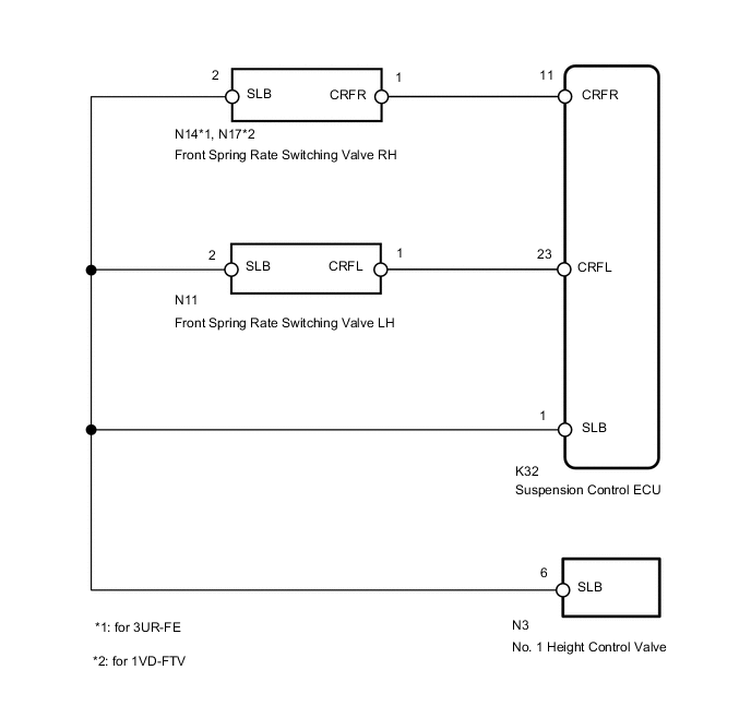
WIRING DIAGRAM
CAUTION / NOTICE / HINT
Note
-
Before performing troubleshooting, inspect the connectors of related circuits.
-
If the suspension control ECU or height control sensor is replaced, the vehicle height offset calibration must be performed Click here.
Tech Tips
Power is supplied to the front suspension control valve and No. 1 height control valve from the suspension control ECU. If a short occurs in the power supply circuit in the No. 1 height control valve, DTC C1736 and/or C1737 will be stored. In this case, DTC C1741, C1742, C1743, C1744, C1753, C1754 and/or C1755 will also be stored.
PROCEDURE
-
PERFORM ACTIVE TEST USING GTS (FRONT SPRING RATE SWITCHING VALVE)
-
Turn the engine switch off.
-
Connect the GTS to the DLC3.
-
Start the engine and turn the GTS on.
-
Enter the following menus: Chassis / AHC / Active Test.
-
Check the operation of the front spring rate switching valve solenoid when operating the solenoid with the GTS.
AHC Tester Display Test Part Control Range Diagnostic Note FR Gas Spring Switch Valve Front spring rate switching valve RH ON or OFF When the FR Gas Spring Switch Valve item of the Active Test is operated, the FR Gas Spring Switch Valve item of the Data List changes to ON/OFF. FL Gas Spring Switch Valve Front spring rate switching valve LH ON or OFF When the FL Gas Spring Switch Valve item of the Active Test is operated, the FL Gas Spring Switch Valve item of the Data List changes to ON/OFF. OK The front spring rate switching valve operates.
NG 
CHECK HARNESS AND CONNECTOR (SUSPENSION CONTROL ECU - FRONT SUSPENSION CONTROL VALVE) Click here
OK 
-
-
RECONFIRM DTC OUTPUT
-
Clear the DTCs Click here.
-
Perform a road test.
-
Check for DTCs.
Result Result Proceed to DTC is output A DTC is not output B
A 
REPLACE SUSPENSION CONTROL ECU Click here
B
USE SIMULATION METHOD TO CHECK Click here
-
-
CHECK HARNESS AND CONNECTOR (SUSPENSION CONTROL ECU - FRONT SUSPENSION CONTROL VALVE)
-
for 3UR-FE:
Disconnect the N14*1 and/or N11*2 front suspension control valve connector.
-
*1: for RH
-
*2: for LH
for 1VD-FTV:
Disconnect the N17*1 and/or N11*2 front suspension control valve connector.
-
*1: for RH
-
*2: for LH
-
-
Disconnect the K32 ECU connector.
-
Measure the resistance according to the value(s) in the table below.
Standard Resistance Tester Connection Condition Specified Condition K32-11 (CRFR) - N14-1 (CRFR)*1
K32-11 (CRFR) - N17-1 (CRFR)*2
Always Below 1 Ω K32-11 (CRFR) - Body ground Always 10 kΩ or higher K32-23 (CRFL) - N11-1 (CRFL) Always Below 1 Ω K32-23 (CRFL) - Body ground Always 10 kΩ or higher K32-1 (SLB) - N14-2 (SLB)*1
K32-1 (SLB) - N17-2 (SLB)*2
Always Below 1 Ω K32-1 (SLB) - N11-2 (SLB) Always Below 1 Ω
-
*1: for 3UR-FE
-
*2: for 1VD-FTV
-
NG
REPAIR OR REPLACE HARNESS OR CONNECTOR
OK
-
-
CHECK HARNESS AND CONNECTOR (BODY GROUND BETWEEN ECU - FRONT SUSPENSION CONTROL VALVE)
-
Disconnect the K32 ECU connector.
-
for 3UR-FE:
Disconnect the N14*1 and/or N11*2 front suspension control valve connector.
-
*1: for RH
-
*2: for LH
for 1VD-FTV:
Disconnect the N17*1 and/or N11*2 front suspension control valve connector.
-
*1: for RH
-
*2: for LH
-
-
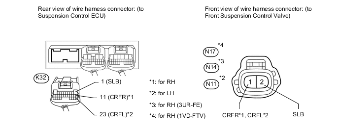
*a Rear view of wire harness connector: (to Suspension Control ECU) *b 1 (SLB) Measure the resistance according to the value(s) in the table below.
Standard Resistance Tester Connection Condition Specified Condition K32-1 (SLB) - Body ground Always 10 kΩ or higher
NG
CHECK HARNESS AND CONNECTOR (BODY GROUND BETWEEN ECU - NO. 1 HEIGHT CONTROL VALVE) Click here
OK
-
-
INSPECT FRONT SUSPENSION CONTROL VALVE
-
for 3UR-FE:
Connect the N14 and/or N11 front suspension control valve connector.
for 1VD-FTV:
Connect the N17 and/or N11 front suspension control valve connector.
-
Disconnect the K32 ECU connector.
-
Measure the resistance according to the value(s) in the table below.
Standard Resistance Tester Connection Condition Specified Condition K32-11 (CRFR) - K32-1 (SLB) at 20°C (68°F) 4.58 to 5.02 Ω K32-23 (CRFL) - K32-1 (SLB) at 20°C (68°F) 4.58 to 5.02 Ω
OK
REPLACE SUSPENSION CONTROL ECU Click here
NG
REPLACE FRONT SUSPENSION CONTROL VALVE Click here
-
-
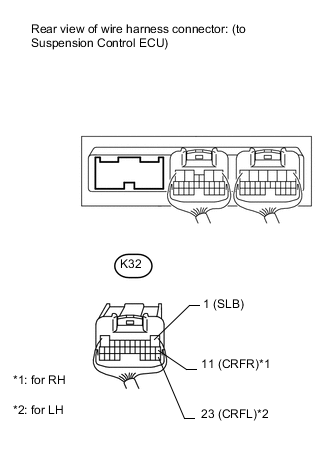
CHECK HARNESS AND CONNECTOR (BODY GROUND BETWEEN ECU - NO. 1 HEIGHT CONTROL VALVE)
-
Disconnect the N3 No. 1 height control valve connector.
-
Disconnect the K32 ECU connector.
-
*a Rear view of wire harness connector: (to Suspension Control ECU) *b 1 (SLB) Measure the resistance according to the value(s) in the table below.
Standard Resistance Tester Connection Condition Specified Condition K32-1 (SLB) - Body ground Always 10 kΩ or higher
NG
REPAIR OR REPLACE HARNESS OR CONNECTOR
OK
-
-
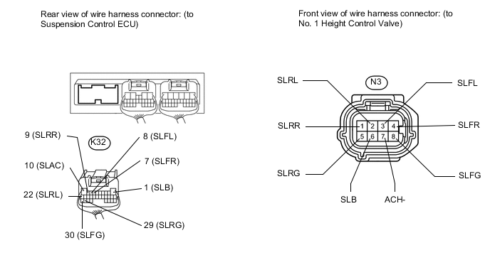
CHECK HARNESS AND CONNECTOR (NO. 1 HEIGHT CONTROL VALVE - SUSPENSION CONTROL ECU)
-
Disconnect the N3 No. 1 height control valve connector.
-
Disconnect the K32 ECU connector.
-
Measure the resistance according to the value(s) in the table below.
Standard Resistance Tester Connection Condition Specified Condition K32-1 (SLB) - N3-6 (SLB) Always Below 1 Ω K32-7 (SLFR) - N3-4 (SLFR) Always Below 1 Ω K32-7 (SLFR) - Body ground Always 10 kΩ or higher K32-8 (SLFL) - N3-3 (SLFL) Always Below 1 Ω K32-8 (SLFL) - Body ground Always 10 kΩ or higher K32-9 (SLRR) - N3-1 (SLRR) Always Below 1 Ω K32-9 (SLRR) - Body ground Always 10 kΩ or higher K32-10 (SLAC) - N3-7 (ACH-) Always Below 1 Ω K32-10 (SLAC) - Body ground Always 10 kΩ or higher K32-22 (SLRL) - N3-2 (SLRL) Always Below 1 Ω K32-22 (SLRL) - Body ground Always 10 kΩ or higher K32-29 (SLRG) - N3-5 (SLRG) Always Below 1 Ω K32-29 (SLRG) - Body ground Always 10 kΩ or higher K32-30 (SLFG) - N3-8 (SLFG) Always Below 1 Ω K32-30 (SLFG) - Body ground Always 10 kΩ or higher
OK
REPLACE NO. 1 HEIGHT CONTROL VALVE Click here
NG
REPAIR OR REPLACE HARNESS OR CONNECTOR
-