FRONT PROPELLER SHAFT ASSEMBLY REASSEMBLY

PROCEDURE
-
INSTALL FRONT PROPELLER SHAFT UNIVERSAL JOINT SPIDER ASSEMBLY
-
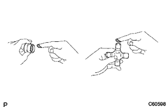
Apply MP grease to a new spider and a new bearings.
Note
Be careful not to apply too much grease.
-
Fit the spider into the flange yoke.
-
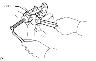
Using SST, install the bearings on the spider.
- SST
- 09332-25010
-
Using SST, adjust both bearings so that the snap ring grooves are at maximum and equal in width.
- SST
- 09332-25010
-
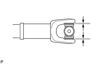
Install 2 new snap rings of equal thickness which will allow 0 mm (0 in.) of axial play.
Tech Tips
Do not reuse the snap rings.
Standard Snap Ring Thickness (for 3UR-FE) Part No. Mark
Color
Specified Condition 90520-29024 - 1.985 to 2.015 mm
(0.0782 to 0.0793 in.)
90520-29025 Light Brown 2.015 to 2.045 mm
(0.0794 to 0.0805 in.)
90520-29026 Blue 2.045 to 2.075 mm
(0.0806 to 0.0816 in.)
90520-29027 - 2.075 to 2.105 mm
(0.0817 to 0.0828 in.)
90520-29039 1 1.98 to 2.00 mm
(0.0780 to 0.0787 in.)
90520-29040 2 2.00 to 2.02 mm
(0.0788 to 0.0795 in.)
90520-29041 3 2.02 to 2.04 mm
(0.0796 to 0.0803 in.)
90520-29042 4 2.04 to 2.06 mm
(0.0804 to 0.0811 in.)
90520-29043 5 2.06 to 2.08 mm
(0.0812 to 0.0818 in.)
90520-29044 6 2.08 to 2.10 mm
(0.0819 to 0.0826 in.)
90520-29045 7 2.10 to 2.12 mm
(0.0827 to 0.0834 in.)
90520-29046 8 2.12 to 2.14 mm
(0.0835 to 0.0842 in.)
90520-29047 
2.14 to 2.16 mm
(0.0843 to 0.0850 in.)
90520-29048 10 2.16 to 218 mm
(0.0851 to 0.0858 in.)
Standard Snap Ring Thickness (for 1VD-FTV) Part No. Mark
Color
Specified Condition 90520-25054 J 2.18 to 2.20 mm
(0.0859 to 0.0866 in.)
90520-25055 K 2.20 to 2.22 mm
(0.0867 to 0.0874 in.)
90520-25056 F 2.22 to 2.24 mm
(0.0875 to 0.0881 in.)
90520-25057 G 2.24 to 2.26 mm
(0.0882 to 0.0899 in.)
90520-25058 H 2.26 to 2.28 mm
(0.0890 to 0.0897 in.)
90520-25039 1 2.28 to 2.30 mm
(0.0898 to 0.0905 in.)
90520-25040 2 2.30 to 2.32 mm
(0.0906 to 0.0913 in.)
90520-25041 - 2.32 to 2.34 mm
(0.0914 to 0.0921 in.)
90520-25042 Brown 2.34 to 2.36 mm
(0.0922 to 0.0929 in.)
90520-25043 Blue 2.36 to 2.38 mm
(0.0930 to 0.0937 in.)
90520-25044 6 2.38 to 2.40 mm
(0.0938 to 0.0944 in.)
90520-25045 7 2.40 to 2.42 mm
(0.0945 to 0.0952 in.)
90520-25046 8 2.42 to 2.44 mm
(0.0953 to 0.0960 in.)
90520-25047 2.44 to 2.46 mm
(0.0961 to 0.0968 in.)
90520-25048 10 2.46 to 2.48 mm
(0.0969 to 0.0976 in.)
90520-25049 A 2.48 to 2.50 mm
(0.0977 to 0.0984 in.)
90520-25050 B 2.50 to 2.52 mm
(0.0985 to 0.0992 in.)
90520-25051 C 2.52 to 2.54 mm
(0.0993 to 0.0999 in.)
90520-25052 D 2.54 to 2.56 mm
(0.1000 to 0.1007 in.)
90520-25053 E 2.56 to 2.58 mm
(0.1008 to 0.1015 in.)
-
Using a hammer, tap the yoke until there is no clearance between the bearing outer race and snap ring.
-
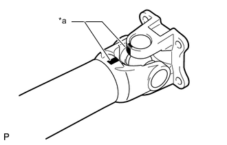
Text in Illustration *a Matchmark Align the matchmarks on the propeller shaft and flange yoke or flange yoke and sleeve yoke.
-
Install the flange yoke to the sleeve yoke or propeller shaft.
Tech Tips
Install 2 new spider bearings and snap rings on the flange yoke side using the procedure described above.
-
-
APPLY MP GREASE
-
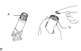
Text in Illustration *a MP Grease Application Area Apply MP grease to the propeller shaft (the edge of the spline) as shown in the illustration.
Amount (Reference) Spline A Amount Silver 44 to 54 g (1.56 to 1.90 oz.) Black 9 to 17 g (0.32 to 0.59 oz.) Tech Tips
The amount of grease differs depending on the color of the spline portion of the sleeve yoke.
-
Align the matchmarks and install the sleeve yoke to the propeller shaft.
Note
-
Do not scratch the spline portion.
-
Make sure that there is no foreign matter.
-
-
-
INSPECT PROPELLER SHAFT GREASE FITTING DIRECTION
Tech Tips
-
When replacing a spider bearing, be sure that the grease fitting hole is facing the direction shown in the illustration.
-
Fill the grease fittings with MP grease.
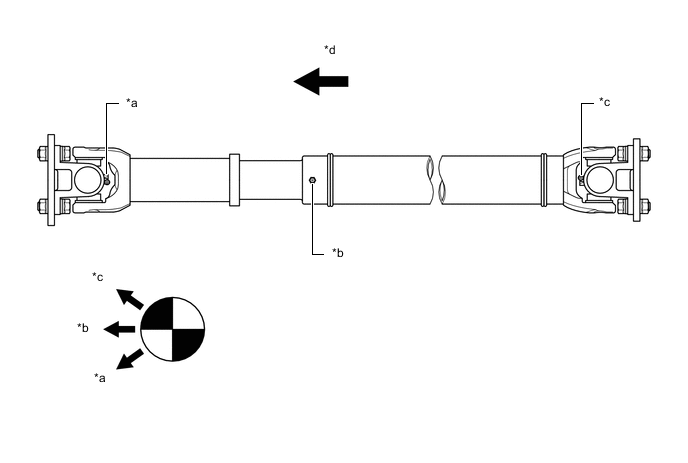
Text in Illustration *a No. 1 Grease Fitting *b No. 2 Grease Fitting *c No. 3 Grease Fitting *d Rear Side -
-
INSPECT SPIDER BEARING