TRANSFER SYSTEM ECU Power Source Circuit
WIRING DIAGRAM
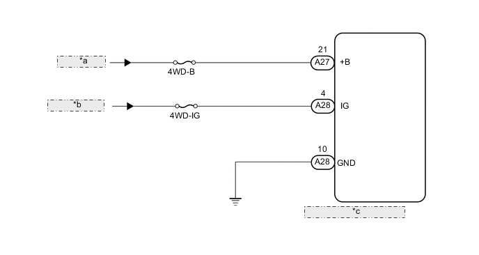
| *a | from Battery |
| *b | from IG1 Relay |
| *c | 4 Wheel Drive Control ECU |
CAUTION / NOTICE / HINT
Note
Inspect the fuses for circuits related to this system before performing the following inspection procedure.
PROCEDURE
-
INSPECT BATTERY
-
Check the battery voltage.
Standard voltage 11 to 14 V Result Result Proceed to OK A NG for 3UR-FE B for 1VD-FTV C
B 
CHECK OR REPLACE CHARGING SYSTEM OR BATTERY Click here
C
CHECK AND REPLACE CHARGING SYSTEM OR BATTERY Click here
A 
-
-
CHECK HARNESS AND CONNECTOR (+B AND IG TERMINAL)
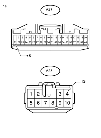
Text in Illustration *a Front view of wire harness connector
(to 4 Wheel Drive Control ECU)
-
Turn the engine switch off.
-
Disconnect the A27 and A28 4 wheel drive control ECU connectors.
-
Measure the voltage according to the value(s) in the table below.
Standard Voltage Tester Connection Condition Specified Condition A27-21 (+B) - Body ground Always 11 to 14 V A28-4 (IG) - Body ground IEngine switch on (IG) 11 to 14 V
NG
REPAIR OR REPLACE HARNESS OR CONNECTOR (+B AND IG CIRCUIT)
OK
-
-
CHECK HARNESS AND CONNECTOR (GND TERMINAL)
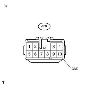
Text in Illustration *a Front view of wire harness connector
(to 4 Wheel Drive Control ECU)
-
Turn the engine switch off.
-
Measure the resistance according to the value(s) in the table below.
Standard Resistance Tester Connection Condition Specified Condition A28-10 (GND) - Body ground Always Below 1 Ω
OK
PROCEED TO NEXT SUSPECTED AREA SHOWN IN PROBLEM SYMPTOMS TABLE Click here
NG
REPAIR OR REPLACE HARNESS OR CONNECTOR (GND CIRCUIT)
-