TRANSFER SYSTEM, Diagnostic DTC:P17A9
| DTC Code | DTC Name |
|---|---|
| P17A9 | Transfer Shift Motor Control Circuit Low |
DESCRIPTION
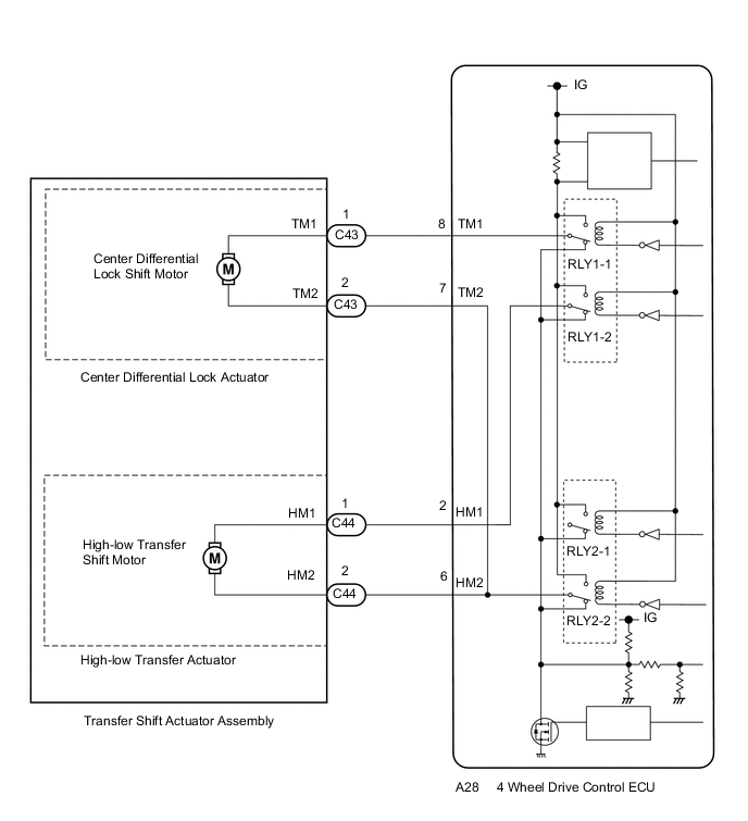
This DTC is output when a short to ground in the high-low transfer shift motor and center differential lock shift motor drive circuit is detected.
| DTC No. | DTC Detection Condition
|
Trouble Area |
|---|---|---|
| P17A9 |
|
|
WIRING DIAGRAM
PROCEDURE
-
CHECK ACTUATOR ASSEMBLY (TRANSFER SHIFT MOTOR OR LOCK SHIFT MOTOR)
-
Disconnect the A28 4 wheel drive control ECU connector.
-
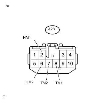
Text in Illustration *a Front view of wire harness connector
(to 4 Wheel Drive Control ECU)
Measure the resistance according to the value(s) in the table below.
Standard Resistance Transfer Shift Actuator Assembly (High-low Transfer Shift Motor) Side Tester Connection Condition Specified Condition A28-2 (HM1) or A28-6 (HM2) - Body ground Always 10 kΩ or higher Transfer Shift Actuator Assembly (Center Differential Lock Shift Motor) Side Tester Connection Condition Specified Condition A28-8 (TM1) or A28-7 (TM2) - Body ground Always 10 kΩ or higher Result Result Proceed to OK for LHD A for RHD B NG (transfer shift actuator assembly (high-low transfer shift motor) side) C NG (transfer shift actuator assembly (center differential lock shift motor) side) D
A 
REPLACE 4 WHEEL DRIVE CONTROL ECU Click here
B
REPLACE 4 WHEEL DRIVE CONTROL ECU Click here
D 
CHECK HARNESS AND CONNECTOR (4 WHEEL DRIVE CONTROL ECU AND TRANSFER SHIFT ACTUATOR ASSEMBLY - BODY GROUND) Click here
C 
-
-
CHECK HARNESS AND CONNECTOR (4 WHEEL DRIVE CONTROL ECU AND TRANSFER SHIFT ACTUATOR ASSEMBLY - BODY GROUND)
-
Disconnect the A28 4 wheel drive control ECU connector.
-
Disconnect the C44 transfer shift actuator assembly connector.
-
Measure the resistance according to the value(s) in the table below.
Standard Resistance Tester Connection Condition Specified Condition A28-2 (HM1) or C44-1 (HM1) - Body ground Always 10 kΩ or higher A28-6 (HM2) or C44-2 (HM2) - Body ground Always 10 kΩ or higher
OK
REPLACE TRANSFER SHIFT ACTUATOR ASSEMBLY Click here
NG
REPAIR OR REPLACE HARNESS OR CONNECTOR
-
-
CHECK HARNESS AND CONNECTOR (4 WHEEL DRIVE CONTROL ECU AND TRANSFER SHIFT ACTUATOR ASSEMBLY - BODY GROUND)
-
Disconnect the A28 4 wheel drive control ECU connector.
-
Disconnect the C43 transfer shift actuator assembly connector.
-
Measure the resistance according to the value(s) in the table below.
Standard Resistance Tester Connection Condition Specified Condition A28-8 (TM1) or C43-1 (TM1) - Body ground Always 10 kΩ or higher A28-7 (TM2) or C43-2 (TM1) - Body ground Always 10 kΩ or higher
OK
REPLACE TRANSFER SHIFT ACTUATOR ASSEMBLY Click here
NG
REPAIR OR REPLACE HARNESS OR CONNECTOR
-