TRANSFER SYSTEM TERMINALS OF ECU
-
CHECK 4 WHEEL DRIVE CONTROL ECU
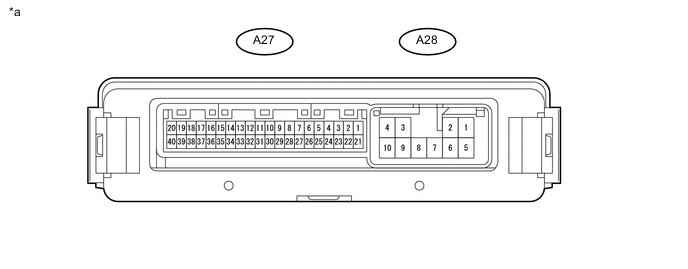
Text in Illustration *a Component with harness connected
(4 Wheel Drive Control ECU)
- -
-
Measure the voltage and resistance according to the value(s) in the table below.
Terminal No. (Symbol) Wiring Color Terminal Description Condition Specified Condition A27-1 (P1) - A28-10 (GND) LG - W-B Center differential lock detection switch input Engine switch on (IG)
Center differential free
10 to 14 V Engine switch on (IG)
Center differential lock
Below 1.5 V A27-5 (TT) - A27-25 (TGND)* G - P Temperature sensor Engine switch on (IG) 0 to 5 V A27-6 (HL3) - A28-10 (GND) R - W-B High-low transfer limit switch input Engine switch on (IG)
Shift lever in N
Transfer high
10 to 14 V Engine switch on (IG)
Shift lever in N
Switching between transfer high and low
Below 1.5 V Engine switch on (IG)
Shift lever in N
Transfer low
10 to 14 V A27-7 (HL2) - A28-10 (GND) P - W-B High-low transfer limit switch input Engine switch on (IG)
Shift lever in N
Transfer high
10 to 14 V Engine switch on (IG)
Shift lever in N
Switching between transfer high and low
10 to 14 V ←→ Below 1.5 V Engine switch on (IG)
Shift lever in N
Transfer low
Below 1.5 V A27-8 (HL1) - A28-10 (GND) BE - W-B High-low transfer limit switch input Engine switch on (IG)
Shift lever in N
Transfer high
Below 1.5 V Engine switch on (IG)
Shift lever in N
Switching between transfer high and low
Below 1.5 V ←→ 10 to 14 V Engine switch on (IG)
Shift lever in N
Transfer low
10 to 14 V A27-9 (TL3) - A28-10 (GND) W - W-B Center differential lock limit switch input Engine switch on (IG)
Center differential free
Below 1.5 V Engine switch on (IG)
Switching center differential between free and lock
Below 1.5 V Engine switch on (IG)
Center differential lock
10 to 14 V A27-10 (TL2) - A28-10 (GND) B - W-B Center differential lock limit switch input Engine switch on (IG)
Center differential free
10 to 14 V Engine switch on (IG)
Switching center differential between free and lock
Below 1.5 V Engine switch on (IG)
Center differential lock
Below 1.5 V A27-13 (LO) - A28-10 (GND) P - W-B Transfer position switch input Engine switch on (IG)
Transfer position switch H4
10 to 14 V Engine switch on (IG)
Transfer position switch L4
Below 1.5 V A27-14 (DL) - A28-10 (GND) L - W-B Center differential lock switch input Engine switch on (IG)
Center differential lock switch not pressed
10 to 14 V Engine switch on (IG)
Center differential lock switch pressed and held
Below 1.5 V A27-16 (L4) - A28-10 (GND) R - W-B L4 output signal Engine switch on (IG)
Transfer high
10 to 14 V Engine switch on (IG)
Transfer low
Below 1.5 V A27-20 (CANH) - A27-40 (CANL) P - W CAN communication line Engine switch off
Cable disconnected from negative (-) battery terminal
54 to 69 Ω A27-21 (+B) - A28-10 (GND) R - W-B ECU power supply Always 11 to 14 V A28-2 (HM1) - A28-10 (GND) B - W-B High-low transfer shift motor output Engine switch on (IG)
Shift lever in N
Transfer position switch switched from H4 to L4
(Switching from transfer high to low)
Below 1.5 V or pulse between 11 to 14 V and below 1.5 V ( waveform 1) Engine switch on (IG)
Shift lever in N
Transfer position switch switched from L4 to H4
(Switching from transfer low to high)
10 to 14 V A28-4 (IG) - A28-10 (GND) V - W-B ECU and actuator power supply Engine switch on (IG) 11 to 14 V A28-6 (HM2) - A28-10 (GND) BR - W-B High-low transfer shift motor output Engine switch on (IG)
Shift lever in N
Transfer position switch switched from H4 to L4
(Switching from transfer high to low)
10 to 14 V Engine switch on (IG)
Shift lever in N
Transfer position switch switched from L4 to H4
(Switching from transfer low to high)
Below 1.5 V or pulse between 11 to 14 V and below 1.5 V ( waveform 1) A28-7 (TM2) - A28-10 (GND) W - W-B Center differential lock shift motor output Engine switch on (IG)
Center differential lock switch pressed to switch from free to lock
(Switching center differential from free to lock)
Below 1.5 V or pulse between 11 to 14 V and below 1.5 V ( waveform 2) Engine switch on (IG)
Center differential lock switch pressed to switch from lock to free
(Switching center differential from lock to free)
10 to 14 V A28-8 (TM1) - A28-10 (GND) R - W-B Center differential lock shift motor output Engine switch on (IG)
Center differential lock switch pressed to switch from free to lock
(Switching center differential from free to lock)
10 to 14 V Engine switch on (IG)
Center differential lock switch pressed to switch from lock to free
(Switching center differential from lock to free)
Below 1.5 V or pulse between 11 to 14 V and below 1.5 V ( waveform 2) A28-10 (GND) - Body ground W-B - Body ground GND Always Below 1 Ω
-
*: w/ Temperature Sensor
-
-
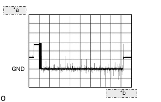
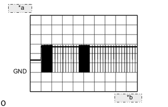
*a 5 V/DIV. *b 200 ms./DIV Waveform 1
-
When a gear is engaged and switching is performed
Item Content Tester Connection A28-2 (HM1) - A28-10 (GND) Tool Setting 5 V/DIV., 200 ms./DIV. Condition Engine switch on (IG)
Shift lever in N
Transfer position switch switched from H4 to L4
(Switching from transfer high to low)
Item Content Tester Connection A28-6 (HM2) - A28-10 (GND) Tool Setting 5 V/DIV., 100 ms./DIV. Condition Engine switch on (IG)
Shift lever in N
Transfer position switch switched from L4 to H4
(Switching from transfer low to high)
-
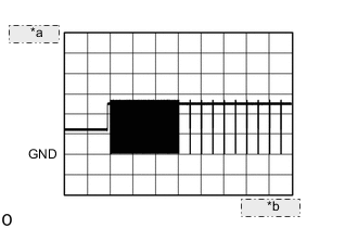
*a 5 V/DIV. *b 1 s./DIV. When a gear is not engaged and switching is not performed
Item Content Tester Connection A28-2 (HM1) - A28-10 (GND) Tool Setting 5 V/DIV., 1 s./DIV. Condition Engine switch on (IG)
Shift lever in N
Transfer position switch switched from H4 to L4
(Switching from transfer high to low)
Item Content Tester Connection A28-6 (HM2) - A28-10 (GND) Tool Setting 5 V/DIV., 1 s./DIV. Condition Engine switch on (IG)
Shift lever in N
Transfer position switch switched from L4 to H4
(Switching from transfer low to high)
-
-
Waveform 2
-
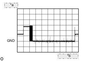
*a 5 V/DIV. *b 100 ms./DIV. When a gear is engaged and switching is performed
Item Content Tester Connection A28-7 (TM2) - A28-10 (GND) Tool Setting 5 V/DIV., 100 ms./DIV. Condition Engine switch on (IG)
Center differential lock switch pressed to switch from free to lock
(Switching center differential from free to lock)
Item Content Tester Connection A28-8 (TM1) - A28-10 (GND) Tool Setting 5 V/DIV., 100 ms./DIV. Condition Engine switch on (IG)
Center differential lock switch pressed to switch from lock to free
(Switching center differential from lock to free)
-
*a 5 V/DIV. *b 2 s./DIV. When a gear is not engaged and switching is not performed
Item Content Tester Connection A28-7 (TM2) - A28-10 (GND) Tool Setting 5 V/DIV., 2 s./DIV. Condition Engine switch on (IG)
Center differential lock switch pressed to switch from free to lock
(Switching center differential from free to lock)
Item Content Tester Connection A28-8 (TM1) - A28-10 (GND) Tool Setting 5 V/DIV., 2 s./DIV. Condition Engine switch on (IG)
Center differential lock switch pressed to switch from lock to free
(Switching center differential from lock to free)
-
-