OIL PUMP INSPECTION

PROCEDURE
-
INSPECT NO. 1 BRAKE PISTON RETURN SPRING SUB-ASSEMBLY
-
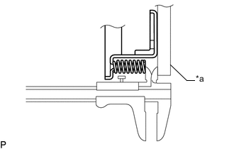
Text in Illustration *a Straightedge Using a vernier caliper and straightedge, measure the distance between the No. 1 brake piston return spring sub-assembly end and the straightedge.
Standard thickness 5.72 mm (0.255 in.)
-
-
INSPECT STATOR SHAFT ASSEMBLY
-
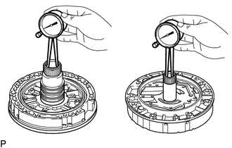
Using a caliper gauge, measure the inside diameter of the stator shaft assembly bushing.
Maximum inside diameter Front side 25.926 mm (1.0207 in.) Rear side 35.251 mm (1.3878 in.) If the inside diameter is more than the maximum, replace the stator shaft assembly.
-
-
INSPECT CLEARANCE OF OIL PUMP ASSEMBLY
-
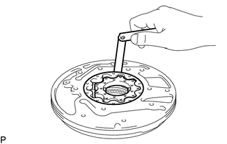
Push the front oil pump driven gear to one side of the front oil pump body sub-assembly.
-
Using a feeler gauge, measure the clearance between the front oil pump driven gear and front oil pump body sub-assembly.
Standard body clearance 0.10 to 0.17 mm (0.00394 to 0.00669 in.) If the body clearance is not as specified, replace the front oil pump drive gear, front oil pump driven gear and front oil pump body sub-assembly.
-
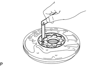
Using a feeler gauge, measure the clearance between the front oil pump driven gear teeth and front oil pump drive gear teeth.
Standard tip clearance 0.065 to 0.171 mm (0.00256 to 0.00673 in.) If the tip clearance is not as specified, replace the front oil pump drive gear, front oil pump driven gear and front oil pump body sub-assembly.
-
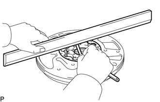
Using a steel straightedge and feeler gauge, measure the clearance between both gears and the straightedge.
Standard side clearance 0.03 to 0.05 mm (0.00119 to 0.00196 in.) If the side clearance is not as specified, replace the front oil pump drive gear, front oil pump driven gear and front oil pump body sub-assembly.
Tech Tips
There are 5 different thicknesses for the front oil pump drive gear and front oil pump driven gear.
Front Oil Pump Drive Gear Thickness Part No. Mark Thickness 35321-60160 A 12.590 to 12.599 mm (0.4957 to 0.4960 in.) 35321-60170 B 12.600 to 12.609 mm (0.4961 to 0.4964 in.) 35321-60180 C 12.610 to 12.620 mm (0.4965 to 0.4968 in.) 35321-60190 D 12.621 to 12.630 mm (0.4969 to 0.4972 in.) 35321-60200 E 12.631 to 12.640 mm (0.4973 to 0.4976 in.) Front Oil Pump Driven Gear Thickness Part No. Mark Thickness 35322-60160 A 12.590 to 12.599 mm (0.4957 to 0.4960 in.) 35322-60170 B 12.600 to 12.609 mm (0.4961 to 0.4964 in.) 35322-60180 C 12.610 to 12.620 mm (0.4965 to 0.4968 in.) 35322-60190 D 12.621 to 12.630 mm (0.4969 to 0.4972 in.) 35322-60200 E 12.631 to 12.640 mm (0.4973 to 0.4976 in.)
-
-
INSPECT OIL PUMP DRIVE GEAR ROTATION
-
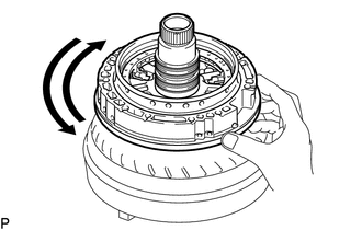
Place the oil pump assembly on the torque converter assembly.
-
Make sure that the drive gear rotates smoothly.
-