AUTOMATIC TRANSMISSION SYSTEM, Diagnostic DTC:U0100
| DTC Code | DTC Name |
|---|---|
| U0100 | Lost Communication with ECM / PCM "A" |
DESCRIPTION
The ECM communicates with the TCM via the Controller Area Network (CAN).
If there is a problem in communication, the TCM stores this DTC.
| DTC No. | DTC Detection Condition
|
Trouble Area |
|---|---|---|
| U0100 |
|
|
WIRING DIAGRAM
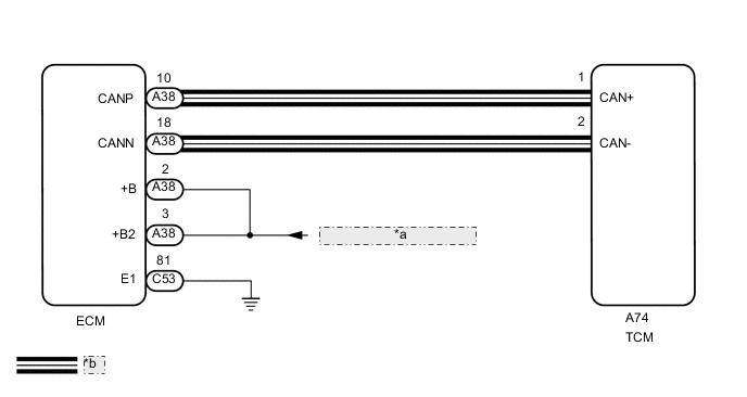
| *a | from EFI MAIN NO. 1 Relay |
| *b | CAN Communication Line |
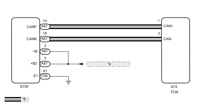
| *a | from EFI MAIN NO. 1 Relay |
| *b | CAN Communication Line |
CAUTION / NOTICE / HINT
Note
Perform registration and/or initialization when parts related to the automatic transmission are replaced Click here.
Tech Tips
-
If the CAN communication system malfunctions, the TCM cannot receive current data from the ECM. In this case, the freeze frame data output from the TCM is not updated, so the data will not be useful for the inspection. However, reading the Data List as the first step in troubleshooting is an effective way to find malfunctions.
-
The malfunctioning area can be checked using the CAN Bus Check function on the GTS.
-
After performing repair, clear the DTCs and perform the following procedure to check that DTCs are not output.
-
Check the battery voltage is 9.5 V or higher.
-
Turn the engine switch on (IG).
-
Check for DTCs again Click here.
PROCEDURE
-
INSPECT ECM
-
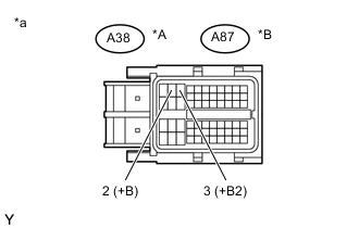
Text in Illustration *A for LHD *B for RHD *a Front view of wire harness connector
(to ECM)
Disconnect the ECM connector.
-
Turn the engine switch on (IG).
-
Measure the voltage according to the value(s) in the table below.
Standard Voltage for LHD Tester Connection Switch Condition Specified Condition A38-2 (+B) - Body ground Engine switch on (IG) 11 to 14 V A38-3 (+B2) - Body ground Engine switch on (IG) 11 to 14 V for RHD Tester Connection Switch Condition Specified Condition A87-2 (+B) - Body ground Engine switch on (IG) 11 to 14 V A87-3 (+B2) - Body ground Engine switch on (IG) 11 to 14 V
NG 
GO TO ECM POWER SOURCE CIRCUIT (ENGINE CONTROL SYSTEM / SFI SYSTEM) Click here
OK 
-
-
CHECK HARNESS AND CONNECTOR (ECM - BODY GROUND)
-
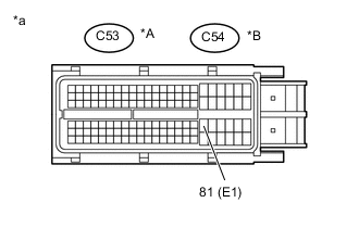
Text in Illustration *A for LHD *B for RHD *a Front view of wire harness connector
(to ECM)
Disconnect the ECM connector.
-
Measure the resistance according to the value(s) in the table below.
Standard Resistance for LHD Tester Connection Condition Specified Condition C53-81 (E1) - Body ground Always Below 1 Ω for RHD Tester Connection Condition Specified Condition C54-81 (E1) - Body ground Always Below 1 Ω
NG
REPAIR OR REPLACE HARNESS OR CONNECTOR
OK
-
-
CHECK HARNESS AND CONNECTOR (ECM - TCM)
-
for LHD:
Disconnect the A38 ECM connector.
-
for RHD:
Disconnect the A87 ECM connector.
-
Disconnect the A74 TCM connector.
-
Measure the resistance according to the value(s) in the table below.
Standard Resistance for LHD Tester Connection Condition Specified Condition A38-10 (CANP) - A74-1 (CAN+) Always Below 1 Ω A38-18 (CANN) - A74-2 (CAN-) Always Below 1 Ω A38-10 (CANP) or A74-1 (CAN+) - Body ground Always 10 kΩ or higher A38-18 (CANN) or A74-2 (CAN-) - Body ground Always 10 kΩ or higher for RHD Tester Connection Condition Specified Condition A87-10 (CANP) - A74-1 (CAN+) Always Below 1 Ω A87-18 (CANN) - A74-2 (CAN-) Always Below 1 Ω A87-10 (CANP) or A74-1 (CAN+) - Body ground Always 10 kΩ or higher A87-18 (CANN) or A74-2 (CAN-) - Body ground Always 10 kΩ or higher
NG
REPAIR OR REPLACE HARNESS OR CONNECTOR
OK
-
-
REPLACE TCM
-
for LHD:
Replace the TCM Click here.
-
for RHD:
Replace the TCM Click here.
NEXT
-
-
CHECK DTC OUTPUT
-
Clear the DTCs Click here.
-
Start the engine.
-
Read the DTCs Click here.
Result Result Proceed to DTCs are not output A DTC U0100 is output B
A
END
B
REPLACE ECM Click here
-