AUTOMATIC TRANSMISSION SYSTEM, Diagnostic DTC:P0705
| DTC Code | DTC Name |
|---|---|
| P0705 | Transmission Range Sensor Circuit Malfunction (PRNDL Input) |
DESCRIPTION
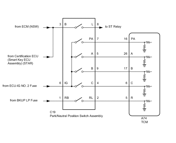
The park/neutral position switch detects the shift lever position and sends signals to the TCM.
| DTC No. | DTC Detection Condition
|
Trouble Area |
|---|---|---|
| P0705 |
|
|
|
||
|
Tech Tips
| Shift Lever Position | A switch | B switch | C switch | PA switch |
|---|---|---|---|---|
| P | ON | OFF | OFF | ON |
| R | ON | ON | OFF | OFF |
| N | OFF | ON | OFF | ON |
| D | OFF | ON | ON | OFF |
| Malfunction Status | A switch | B switch | C switch | PA switch |
|---|---|---|---|---|
| No signal | OFF | OFF | OFF | OFF |
| Implausible combination | ON | ON | OFF | ON |
| ON | ON | ON | ON | |
| ON | OFF | ON | ON | |
| ON | OFF | ON | OFF | |
| OFF | OFF | ON | ON | |
| OFF | OFF | OFF | ON | |
| ON | OFF | OFF | OFF | |
| OFF | OFF | ON | OFF | |
| ON | ON | ON | OFF | |
| OFF | ON | OFF | OFF | |
| Uncertain D position | OFF | ON | ON | ON |
MONITOR DESCRIPTION
This DTC indicates a problem with the park/neutral position switch assembly or the wire harness in the park/neutral position switch assembly circuit.
The park/neutral position switch assembly detects the shift lever position and sends signals to the TCM.
For safety, the park/neutral position switch assembly detects the shift lever position so that the engine can be started only when the shift lever is in P or N.
The park/neutral position switch assembly sends signals to the TCM according to the shift lever position (P, N, R or D).
The TCM determines that there is a problem with the switch or related parts if a malfunction occurs in the park/neutral position switch signal. The TCM will illuminate the MIL and store the DTC.
WIRING DIAGRAM
CAUTION / NOTICE / HINT
Note
-
Perform registration and/or initialization when parts related to the automatic transmission are replaced Click here.
-
Inspect the fuses for circuits related to this system before performing the following inspection procedure.
Tech Tips
After the repair, clear the DTCs and perform the following procedure to check that DTCs are not output.
-
Turn the engine switch on (IG).*1
-
Wait with the shift lever in each position (P, R, N and D) for 5 seconds or more.*2
-
Drive the vehicle 30 km/h (19 mph) or more for 30 seconds or more.*3
-
Turn the engine switch off.
-
Perform steps (*1) through (*3) again.
-
Check for DTCs again Click here.
PROCEDURE
-
ADJUST PARK/NEUTRAL POSITION SWITCH ASSEMBLY
-
Adjust the park/neutral position switch assembly Click here.
NEXT 
-
-
ADJUST TRANSMISSION FLOOR SHIFT ASSEMBLY
-
Adjust the transmission floor shift assembly Click here.
NEXT
-
-
READ VALUE USING GTS (SHIFT SW STATUS)
-
Connect the GTS to the DLC3.
-
Turn the engine switch on (IG).
-
Turn the GTS on.
-
Enter the following menus: Powertrain / ECT / Data List.
-
According to the display on the GTS, read the Data List.
ECT Tester Display Measurement Item/Range Normal Condition Diagnostic Note Shift SW Status (P Range) Park/neutral position switch status/
ON or OFF
-
ON: Shift lever is in P
-
OFF: Shift lever is not in P
When shift lever position displayed on the GTS differs from actual position, adjustment of park/neutral position switch assembly or shift cable may be incorrect. Shift SW Status (R Range) Park/neutral position switch status/
ON or OFF
-
ON: Shift lever is in R
-
OFF: Shift lever is not in R
When shift lever position displayed on the GTS differs from actual position, adjustment of park/neutral position switch assembly or shift cable may be incorrect. Shift SW Status (N Range) Park/neutral position switch status/
ON or OFF
-
ON: Shift lever is in N
-
OFF: Shift lever is not in N
When shift lever position displayed on the GTS differs from actual position, adjustment of park/neutral position switch assembly or shift cable may be incorrect. Shift SW Status (D Range) Park/neutral position switch status/
ON or OFF
-
ON: Shift lever is in D or S
-
OFF: Shift lever is not in D or S
When shift lever position displayed on the GTS differs from actual position, adjustment of park/neutral position switch assembly or shift cable may be incorrect. Result Result Proceed to Data List value is not within the normal condition A Data List value is within the normal condition B -
B 
INCORRECT ADJUSTMENT
A
-
-
CHECK PARK/NEUTRAL POSITION SWITCH ASSEMBLY (POWER SOURCE)
-
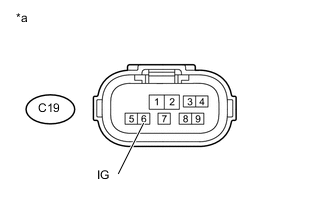
Text in Illustration *a Front view of wire harness connector
(to Park/Neutral Position Switch Assembly)
Disconnect the park/neutral position switch assembly connector.
-
Turn the engine switch on (IG).
-
Measure the voltage according to the value(s) in the table below.
Standard Voltage Tester Connection Switch Condition Specified Condition C19-6 (IG) - Body ground Engine switch on (IG) 11 to 14 V
NG
REPAIR OR REPLACE HARNESS OR CONNECTOR (PARK/NEUTRAL POSITION SWITCH ASSEMBLY - BATTERY)
OK
-
-
INSPECT PARK/NEUTRAL POSITION SWITCH ASSEMBLY
-
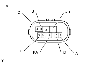
Text in Illustration *a Component without harness connected
(Park/Neutral Position Switch Assembly)
Disconnect the park/neutral position switch assembly connector.
-
Measure the resistance according to the value(s) in the table below.
Standard Resistance Tester Connection Condition Specified Condition 6 (IG) - 4 (C) Shift lever in D and S Below 1 Ω 6 (IG) - 5 (A) Shift lever in P and R Below 1 Ω 6 (IG) - 7 (PA) Shift lever in P and N Below 1 Ω 6 (IG) - 9 (B) Shift lever in R, N, D and S Below 1 Ω 6 (IG) - 4 (C) Shift lever not in D and S 10 kΩ or higher 6 (IG) - 5 (A) Shift lever not in P and R 10 kΩ or higher 6 (IG) - 7 (PA) Shift lever not in P and N 10 kΩ or higher 6 (IG) - 9 (B) Shift lever not in R, N, D and S 10 kΩ or higher 1 (RB) - 4 (C), 5 (A), 7 (PA) and 9 (B) Shift lever in P, R, N, D and S 10 kΩ or higher 3 (B) - 4 (C), 5 (A), 7 (PA) and 9 (B) Shift lever in P, R, N, D and S 10 kΩ or higher
NG
REPLACE PARK/NEUTRAL POSITION SWITCH ASSEMBLY Click here
OK
-
-
CHECK HARNESS AND CONNECTOR (PARK/NEUTRAL POSITION SWITCH ASSEMBLY - TCM)
-
Disconnect the C19 park/neutral position switch assembly connector.
-
Disconnect the A74 TCM connector.
-
Measure the resistance according to the value(s) in the table below.
Standard Resistance Tester Connection Condition Specified Condition C19-4 (C) - A74-6 (C) Always Below 1 Ω C19-5 (A) - A74-26 (A) Always Below 1 Ω C19-7 (PA) - A74-16 (PA) Always Below 1 Ω C19-9 (B) - A74-17 (B) Always Below 1 Ω C19-4 (C) or A74-6 (C) - Body ground Always 10 kΩ or higher C19-5 (A) or A74-26 (A) - Body ground Always 10 kΩ or higher C19-7 (PA) or A74-16 (PA) - Body ground Always 10 kΩ or higher C19-9 (B) or A74-17 (B) - Body ground Always 10 kΩ or higher Result Result Proceed to OK (for LHD) A OK (for RHD) B NG C
A
REPLACE TCM Click here
B
REPLACE TCM Click here
C
REPAIR OR REPLACE HARNESS OR CONNECTOR
-