AUTOMATIC TRANSMISSION UNIT REASSEMBLY

PROCEDURE
-
BEARING POSITION
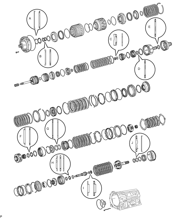
Bearing and Race Diameter Mark Front Race Diameter Inside / Outside Thrust Bearing Diameter Inside / Outside Rear Race Diameter Inside / Outside A 74.26 to 74.56 mm (2.924 to 2.935 in.) / 87.39 to 87.74 mm (3.441 to 3.454 in.) 71.96 to 72.26 mm (2.834 to 2.844 in.) / 85.25 to 85.60 mm (3.357 to 3.370 in.) - B 38.0 to 38.3 mm (1.497 to 1.507 in.) / 53.9 to 54.1 mm (2.123 to 2.129 in.) 36.45 to 36.70 mm (1.44 to 1.45 in.) / 52.10 to 52.60 mm (2.06 to 2.07 in.) - C - 21.05 to 21.30 mm (0.829 to 0.838 in.) / 39.63 to 39.88 mm (1.561 to 1.570 in.) 22.80 to 23.10 mm (0.898 to 0.909 in.) / 44.5 to 44.75 mm (1.75 to 1.76 in.) D - 39.45 to 39.7 mm (1.55 to 1.56 in.) / 60.50 to 60.75 mm (2.38 to 2.39 in.) - E - 46.45 to 46.70 mm (1.83 to 1.84 in.) / 64.30 to 64.55 mm (2.53 to 2.54 in.) - F 55.00 to 55.20 mm (2.165 to 2.173 in.) / 68.80 to 69.30 mm (2.71 to 2.73 in.) 54.55 to 54.8 mm (2.15 to 2.16 in.) / 70.0 to 70.5 mm (2.76 to 2.77 in.) - G - 65.35 to 65.60 mm (2.57 to 2.58 in.) / 85.60 to 85.95 mm (3.37 to 3.38 in.) 62.85 to 63.10 mm (2.47 to 2.48 in.) / 82.30 to 82.60 mm (3.24 to 3.25 in.) H 39.67 to 39.87 mm (1.56 to 1.57 in.) / 56.50 to 57.00 mm (2.22 to 2.24 in.) 36.45 to 36.61 mm (1.437 to 1.441 in.) / 56.62 to 56.92 mm (2.23 to 2.24 in.) 36.45 to 36.70 mm (1.435 to 1.445 in.) / 56.50 to 57.00 mm (2.22 to 2.24 in.) I 21.05 to 21.30 mm (0.829 to 0.839 in.) / 39.50 to 39.80 mm (1.56 to 1.57 in.) 23.20 to 23.40 mm (0.913 to 0.921 in.) / 43.90 to 44.15 mm (1.73 to 1.74 in.) - J - 43.60 to 43.85 mm (1.72 to 1.73 in.) / 62.30 to 62.80 mm (2.45 to 2.47 in.) 47.15 to 47.40 mm (1.86 to 1.87 in.) / 66.90 to 67.10 mm (2.63 to 2.64 in.) -
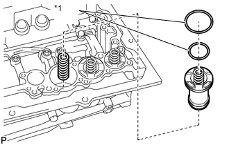
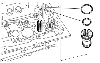
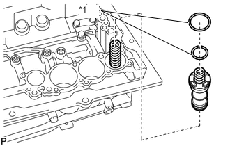
INSTALL 1ST AND REVERSE BRAKE PISTON
-
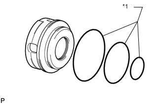
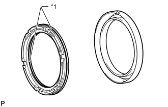
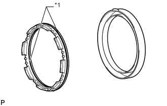
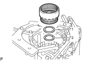
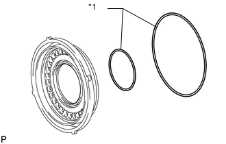
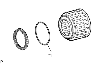
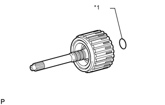
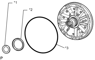
Text in Illustration *1 O-ring Coat 3 new O-rings with ATF and install them to the 1st and reverse brake piston.
-
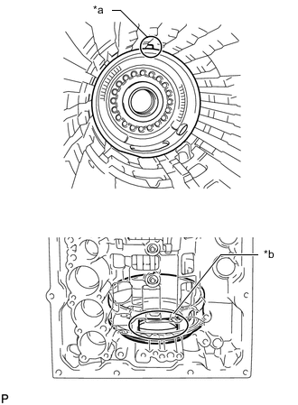
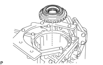
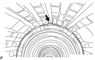
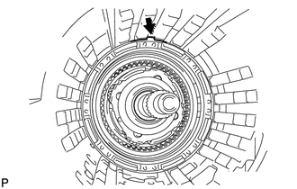
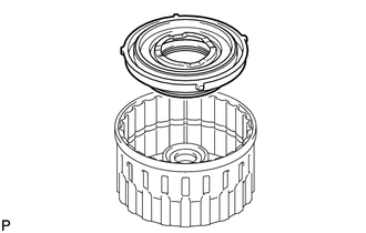
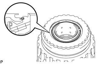
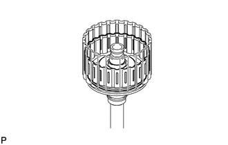
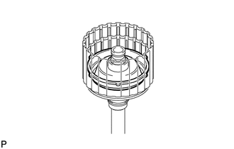
Text in Illustration *a Protrusion *b Parking Hole Install the 1st and reverse brake piston to the transmission case.
Note
-
Be careful not to damage the O-ring.
-
Make sure that the parking hole of the brake piston is on the bottom by engaging the brake piston protrusion and the transmission case spline grooves.
-
-
-
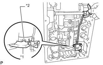
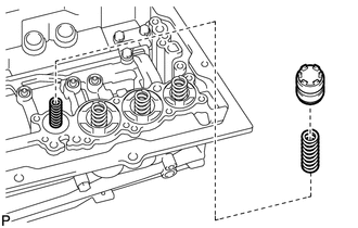
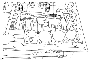
INSTALL 1ST AND REVERSE BRAKE RETURN SPRING SUB-ASSEMBLY
-
Place the 1st and reverse brake return spring sub-assembly onto the 1st and reverse brake piston.
-
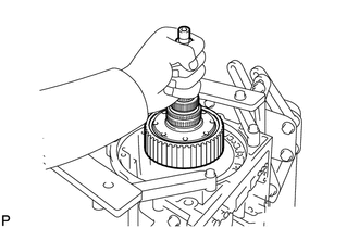
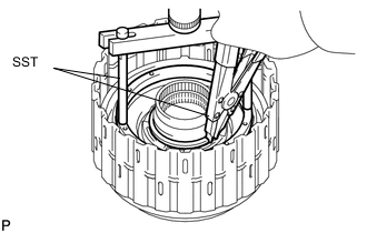
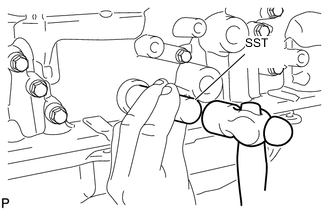
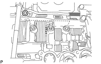
Place SST on the 1st and reverse brake return spring sub-assembly and compress the 1st and reverse brake return spring sub-assembly.
- SST
- 09380-60011 ( 09381-06030, 09381-06040, 09381-06080, 09381-06120, 09381-06130, 09381-05040, 09381-05050 )
-
Using SST, install the snap ring.
- SST
- 09350-30020 ( 09350-07070 )
-
-
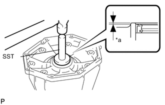
SELECT NO. 4 BRAKE FLANGE
-
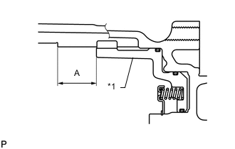
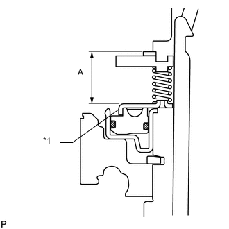
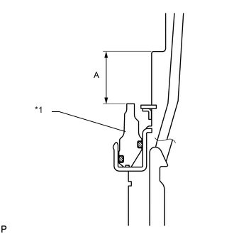
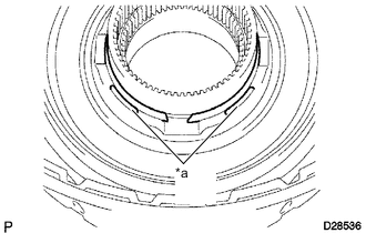
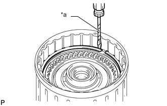
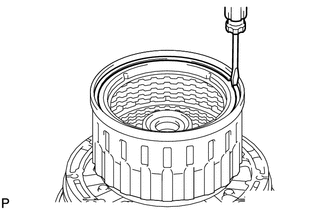
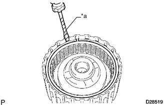
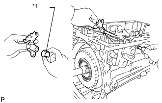
Text in Illustration *1 1st and Reverse Brake Piston Measure distance A (from the tip of the 1st and reverse brake piston to the step in the transmission case) in the illustration.*1
Tech Tips
Standard distance A: 27.82 to 28.42 mm (1.10 to 1.11 in.)
-
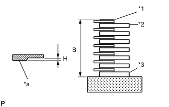
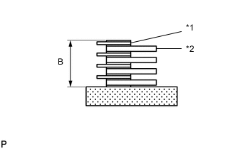
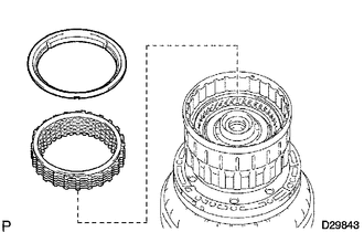
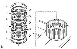
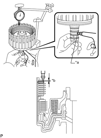
Text in Illustration *1 No. 4 Brake Disc *2 Plate *3 No. 4 Brake Flange *a Selected No. 4 brake flange Assemble the flange, No. 4 brake flange, 7 No. 4 brake discs and 6 plates, and measure distance B in the illustration.*2
Tech Tips
Standard distance B: 25.98 to 27.01 mm (1.03 to 1.06 in.)
-
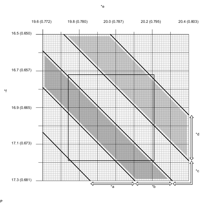
Apply the A and B measurements taken in *1 and *2 to the graph below. Use A for the X axis and B for the Y axis, and then choose the No. 4 brake flange indicated by the graph point.
-
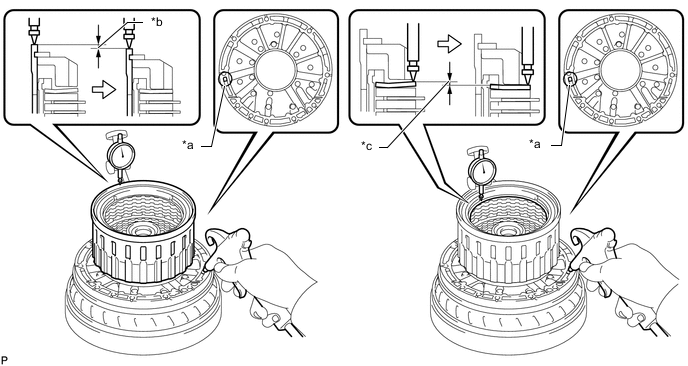
Measure length H of the selected No. 4 brake flange as shown in the illustration.
Tech Tips
Make sure that when the B measurement and the H dimension of the selected No. 4 brake flange are subtracted from the A measurement, the value is 0.961 to 1.261 mm (0.0379 to 0.0496 in.).
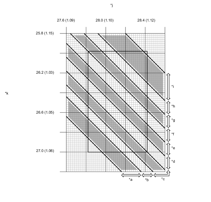
Text in Illustration *a Mark 0 *b Mark 1 *c Mark 3 *d Mark 4 *e Mark 5 *f Mark 7 *g Mark 8 *h Mark 10 *i Mark 11 *j Distance A mm (in.) *k Distance B mm (in.) - - Selected No. 4 Brake Flange Length H Mark Length H 0 0 mm (0 in.) 1 0.09 to 0.25 mm (0.00355 to 0.00984 in.) 3 0.23 to 0.39 mm (0.00906 to 0.0153 in.) 4 0.37 to 0.53 mm (0.0146 to 0.0208 in.) 5 0.51 to 0.67 mm (0.0201 to 0.0263 in.) 7 0.65 to 0.81 mm (0.0256 to 0.0318 in.) 8 0.79 to 0.95 mm (0.0312 to 0.0374 in.) 10 0.93 to 1.09 mm (0.0367 to 0.0429 in.) 11 1.07 to 1.23 mm (0.0422 to 0.0484 in.)
-
-
INSTALL REAR PLANETARY GEAR ASSEMBLY
-
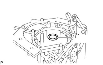
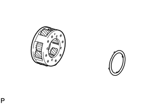
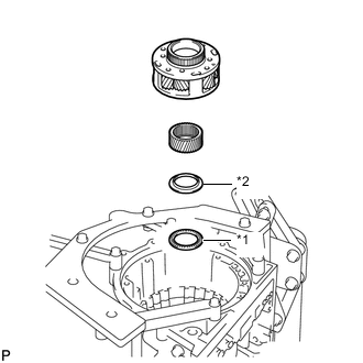
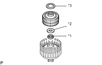
Text in Illustration *1 Race (J) Install the thrust bearing race.
Tech Tips
Use a small amount of MP grease to make the thrust bearing race stay securely in place.
Bearing Race Diameter Item Inside Outside Race (J) 47.15 to 47.40 mm (1.857 to 1.866 in.) 66.90 to 67.10 mm (2.634 to 2.641 in.) -
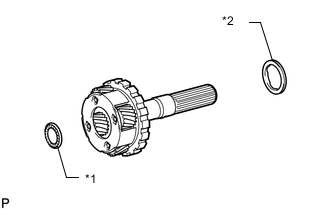
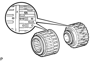
Text in Illustration *1 Bearing (I) *2 Bearing (J) Install the 2 thrust needle roller bearings to the rear planetary gear assembly.
Bearing Diameter Item Inside Outside Bearing (I) 23.20 to 23.40 mm (0.913 to 0.921 in.) 43.90 to 44.15 mm (1.73 to 1.74 in.) Bearing (J) 43.60 to 43.85 mm (1.72 to 1.73 in.) 62.30 to 62.80 mm (2.45 to 2.47 in.) Tech Tips
Use a small amount of MP grease to make the thrust needle roller bearings stay securely in place.
-
Install the rear planetary gear assembly.
-
-
INSTALL BRAKE PLATE STOPPER SPRING
-
INSTALL REAR PLANETARY RING GEAR
-
Install the rear planetary ring gear flange to the rear planetary ring gear.
-
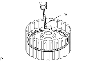
Using a screwdriver, install the snap ring.
-
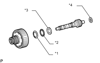
Text in Illustration *1 Front Race (H) *2 Bearing (H) *3 Rear Race (H) *4 Race (I) Install the 3 thrust bearing races, thrust needle roller bearing and rear planetary ring gear together with the rear planetary ring gear flange to the intermediate shaft.
Tech Tips
Use a small amount of MP grease to make the thrust needle roller bearings and races stay securely in place.
Bearing and Race Diameter Item Inside Outside Front race (H) 39.67 to 39.87 mm (1.56 to 1.57 in.) 56.50 to 57.00 mm (2.22 to 2.24 in.) Bearing (H) 36.45 to 36.61 mm (1.437 to 1.441 in.) 56.62 to 56.92 mm (2.23 to 2.24 in.) Rear race (H) 36.45 to 36.70 mm (1.435 to 1.445 in.) 56.50 to 57.00 mm (2.22 to 2.24 in.) Race (I) 21.05 to 21.30 mm (0.829 to 0.839 in.) 39.50 to 39.80 mm (1.56 to 1.57 in.)
-
-
INSTALL INTERMEDIATE SHAFT WITH REAR PLANETARY RING GEAR FLANGE AND REAR PLANETARY RING GEAR
-
Install the intermediate shaft with rear planetary ring gear flange and rear planetary ring gear to the transmission case.
-
-
INSTALL NO. 4 BRAKE DISC
*1 S/F
-
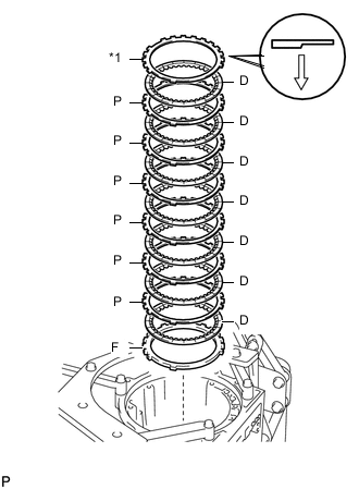
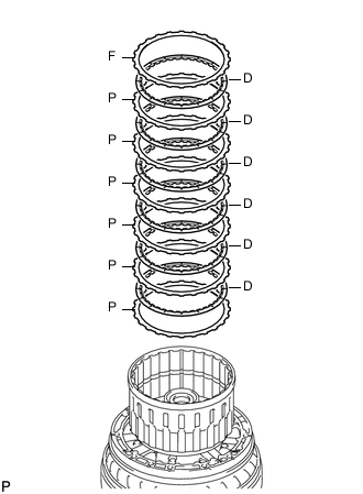
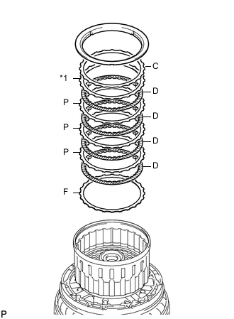
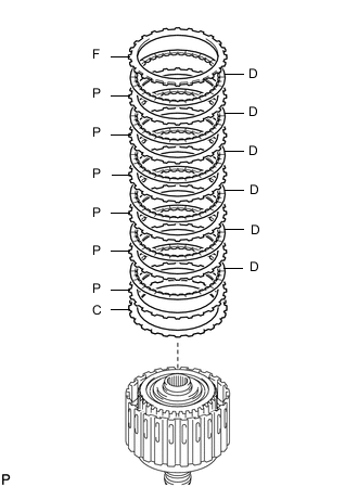
Install the flange, 7 No. 4 brake discs, 6 plates and selected No. 4 brake flange.
Install in order F - D - P - D - P - D - P - D - P - D - P - D - P - D - S/F Tech Tips
F = Flange
D = No. 4 Brake Disc
P = Plate
S/F = Selected No. 4 brake flange
Note
Before assembling new discs, soak them in ATF for at least 2 hours.
-
-
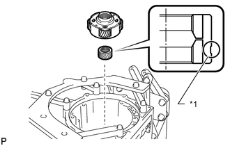
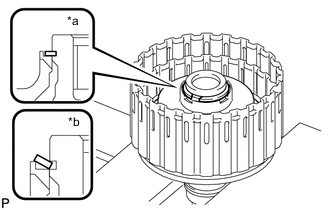
INSTALL 1-WAY CLUTCH INNER RACE
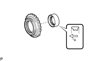
Text in Illustration *a Front
-
Install the No. 3 1-way clutch inner race to the No. 3 1-way clutch assembly.
Note
Be sure to install the 1-way clutch inner race so that it is facing in the proper direction.
-
-
INSPECT NO. 3 1-WAY CLUTCH ASSEMBLY
-
INSTALL NO. 3 1-WAY CLUTCH ASSEMBLY
-
Install the No. 3 1-way clutch assembly to the transmission case.
-
Using SST, install the snap ring.
- SST
- 09350-30020 ( 09350-07060 )
-
-
INSTALL NO. 2 BRAKE PISTON
-
Text in Illustration *1 O-ring Coat 2 new O-rings with ATF and install them to the No. 2 brake piston.
-
Press the No. 2 brake piston into the No. 2 brake cylinder with both hands.
Note
Be careful not to damage the O-rings.
-
-
INSTALL NO. 2 BRAKE CYLINDER WITH NO. 2 BRAKE PISTON
-
Install the No. 2 brake cylinder with No. 2 brake piston to the transmission case.
Note
-
-
When installing the No. 2 brake cylinder with No. 2 brake piston to the transmission case, align the cylinder claw with the groove in the top of the case.
-
Make sure the No. 2 brake cylinder with No. 2 brake piston is securely inserted into the transmission case.
-
-
-
SELECT NO. 2 BRAKE FLANGE
-
Install the No. 2 brake piston return spring sub-assembly and flange to the No. 2 brake piston.
-
Place SST on the No. 2 brake flange and compress the No. 2 brake piston return spring sub-assembly.
- SST
- 09380-60011 ( 09381-06010, 09381-06020, 09381-06050, 09381-06070, 09381-06090, 09381-06120 )
-
Using a screwdriver, install the snap ring to the transmission case.
-
Text in Illustration *1 No. 2 Brake Piston Return Spring Measure distance A (from the top surface of the snap ring to the top surface of the No. 2 brake piston return spring sub-assembly) in the illustration.*1
Tech Tips
Standard distance A: 21.00 to 21.76 mm (0.827 to 0.856 in.)
-
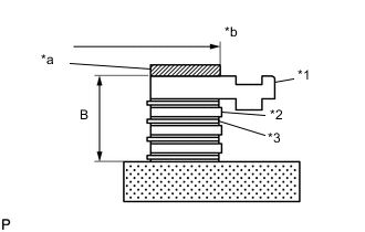
Text in Illustration *1 Flange *2 Plate *3 No. 2 Brake Disc *a Fixture *b 165.2 mm or less Assemble the 4 No. 2 brake discs, 3 plates and flange as shown in the illustration. Then, with a fixture of 165.2 mm (6.50 in.) or less placed on the flange, measure distance B.*2
Tech Tips
Standard distance B: 16.54 to 17.15 mm (0.652 to 0.675 in.)
-
Apply the A and B measurements taken in *1 and *2 to the graph below. Use A for the X axis and B for the Y axis, and then choose the No. 2 brake flange indicated by the graph point.
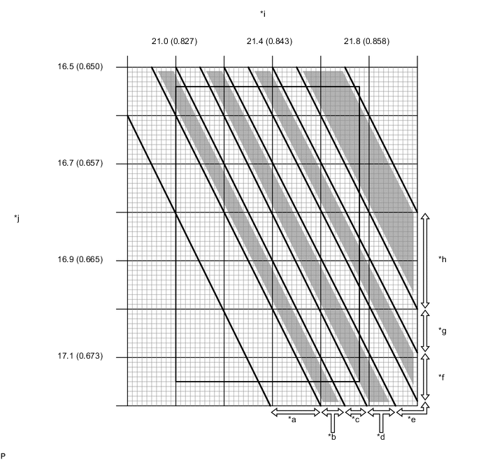
Text in Illustration *a Mark 0 *b Mark 1 *c Mark 2 *d Mark 3 *e Mark 4 *f Mark 5 *g Mark 6 *h Mark 7 *i Distance A mm (in.) *j Distance B mm (in.) Tech Tips
Make sure that when the B measurement and selected No. 2 brake flange thickness are subtracted from the A measurement, the value is 2.20 to 2.50 mm (0.0867 to 0.0984 in.).
Flange Thickness Mark Thickness 0 1.95 to 2.05 mm (0.0768 to 0.0807 in.) 1 2.05 to 2.15 mm (0.0808 to 0.0846 in.) 2 2.15 to 2.25 mm (0.0847 to 0.0885 in.) 3 2.25 to 2.35 mm (0.0886 to 0.0925 in.) 4 2.35 to 2.45 mm (0.0926 to 0.0964 in.) 5 2.45 to 2.55 mm (0.0965 to 0.100 in.) 6 2.55 to 2.65 mm (0.101 to 0.104 in.) 7 2.65 to 2.75 mm (0.105 to 0.108 in.) -
Remove the snap ring, flange and No. 2 brake piston return spring sub-assembly from the transmission case.
-
-
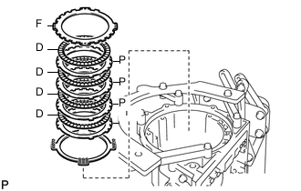
INSTALL NO. 2 BRAKE DISC SET
*1 S/F
-
Install the No. 2 brake piston return spring, selected No. 2 brake flange, 4 No. 2 brake discs, 3 plates and flange.
Install in order S/F - D - P - D - P - D - P - D - F Tech Tips
S/F = Selected flange
D = No. 2 brake disc
P = Plate
F = Flange
Note
Before assembling new No. 2 brake discs, soak them in ATF for at least 2 hours.
-
Place SST on the flange and compress the No. 2 brake piston return spring sub-assembly.
- SST
- 09380-60011 ( 09381-06010, 09381-06020, 09381-06050, 09381-06070, 09381-06090, 09381-06120 )
-
Using a screwdriver, install the snap ring to the transmission case.
Note
Be careful not to damage the transmission case.
Tech Tips
Wrap the tip of the screwdriver with protective tape before use.
-
-
INSTALL CENTER PLANETARY GEAR ASSEMBLY
-
Text in Illustration *1 Return Spring Retainer Install the center planetary sun gear and center planetary gear assembly to the transmission case.
Note
Make sure to install the center planetary sun gear with the groove facing the transmission case.
-
-
INSTALL NO. 1 BRAKE PISTON
-
Text in Illustration *1 O-ring Coat 2 new O-rings with ATF and install them to the No. 1 brake piston.
-
Press the No. 1 brake piston into the No. 1 brake cylinder with both hands.
Note
Be careful not to damage the O-rings.
-
-
INSTALL NO. 1 BRAKE CYLINDER WITH NO. 1 BRAKE PISTON
-
Install the No. 1 brake cylinder with No. 1 brake piston and brake piston return spring sub-assembly to the transmission case.
Note
-
-
When installing the No. 1 brake cylinder with No. 1 brake piston to the transmission case, align the cylinder claw with the groove in the top of the case
-
Make sure the No. 1 brake cylinder with No. 1 brake piston is securely inserted into the transmission case.
-
-
Place SST on the brake piston return spring sub-assembly and compress the brake piston return spring sub-assembly.
- SST
- 09380-60011 ( 09381-06010, 09381-06020, 09381-06050, 09381-06060, 09381-06090, 09381-06100, 09381-06110, 09381-06120 )
-
Using a screwdriver, install the snap ring to the transmission case.
Note
Be careful not to damage the transmission case.
Tech Tips
Wrap the tip of the screwdriver with protective tape before use.
-
-
SELECT NO. 1 BRAKE FLANGE
-
Text in Illustration *1 No. 1 Brake Piston Measure distance A (from the step in the transmission case to the tip of the No. 1 brake piston) in the illustration.*1
Tech Tips
Standard distance A: 19.74 to 20.22 mm (0.778 to 0.796 in.)
-
Text in Illustration *1 No. 1 Brake Disc *2 Plate Assemble the 4 plates and 4 No. 1 brake discs and measure distance B in the illustration.*2
Tech Tips
Standard distance B: 16.72 to 17.19 mm (0.659 to 0.676 in.)
-
Apply the A and B measurements taken in *1 and *2 to the graph below. Use A for the X axis and B for the Y axis, and then choose the No. 1 brake flange indicated by the graph point.
Text in Illustration *a Mark 0 *b Mark 1 *c Mark 2 *d Mark 3 *e Distance A mm (in.) *f Distance B mm (in.) Tech Tips
Make sure that when the B measurement and selected flange thickness are subtracted from the A measurement, the value is 0.56 to 0.86 mm (0.0221 to 0.0338 in.).
Flange Thickness Mark Thickness 0 1.95 to 2.05 mm (0.0768 to 0.0807 in.) 1 2.15 to 2.25 mm (0.0847 to 0.0885 in.) 2 2.35 to 2.45 mm (0.0926 to 0.0964 in.) 3 2.55 to 2.65 mm (0.101 to 0.104 in.)
-
-
INSTALL CENTER PLANETARY RING GEAR
-
Install the front planetary ring gear flange to the center planetary ring gear.
-
Using a screwdriver, install the snap ring.
-
-
INSTALL FRONT PLANETARY RING GEAR
-
Install the front planetary ring gear to the center planetary ring gear.
-
-
INSTALL FRONT PLANETARY RING GEAR WITH FRONT PLANETARY RING GEAR FLANGE SUB-ASSEMBLY AND CENTER PLANETARY RING GEAR
-
Text in Illustration *1 Bearing (G) *2 Race (G) Install the thrust bearing race and thrust needle roller bearing.
Tech Tips
Use a small amount of MP grease to make the thrust needle roller bearing and thrust bearing race stay securely in place.
Bearing and Race Diameter Item Inside Outside Race (G) 62.85 to 63.10 mm (2.47 to 2.48 in.) 82.30 to 82.60 mm (3.24 to 3.25 in.) Bearing (G) 65.35 to 65.60 mm (2.57 to 2.58 in.) 85.60 to 85.95 mm (3.37 to 3.38 in.) -
Install the front planetary ring gear with the front planetary ring gear flange sub-assembly and center planetary ring gear to the transmission case.
-
-
INSTALL FRONT PLANETARY GEAR ASSEMBLY
-
Install the No. 2 planetary carrier thrust washer to the front planetary gear assembly.
Tech Tips
Use a small amount of MP grease to make the No. 2 planetary carrier thrust washer stay securely in place.
-
Text in Illustration *1 Bearing (F) *2 Race (F) Install the thrust needle roller bearing, thrust bearing race, front planetary sun gear and front planetary gear assembly.
Tech Tips
Use a small amount of MP grease to make the thrust needle roller bearing and thrust bearing race stay securely in place.
Bearing Diameter Item Inside Outside Bearing (F) 54.55 to 54.80 mm (2.15 to 2.16 in.) 70.00 to 70.50 mm (2.76 to 2.77 in.) Race (F) 55.00 to 55.20 mm (2.165 to 2.173 in.) 68.80 to 69.30 mm (2.71 to 2.73 in.)
-
-
INSTALL 1-WAY CLUTCH INNER RACE SUB-ASSEMBLY
-
Install the No. 1 planetary carrier thrust washer to the 1-way clutch inner race sub-assembly, and then install them to the 1-way clutch assembly.
Tech Tips
Use a small amount of MP grease to make the No. 1 planetary carrier thrust washer stay securely in place.
-
-
INSPECT 1-WAY CLUTCH ASSEMBLY
-
INSTALL 1-WAY CLUTCH ASSEMBLY WITH 1-WAY CLUTCH INNER RACE SUB-ASSEMBLY
-
Install the 1-way clutch assembly with the 1-way clutch inner race sub-assembly to the transmission case.
-
-
INSTALL NO. 1 BRAKE DISC SET
-
Install the 4 plates, 4 No. 1 brake discs and No. 1 brake flange.
Install in order P - D - P - D - P - D - P - D - F Tech Tips
P = Plate
D = No. 1 brake disc
F = No. 1 brake flange
Note
Before assembling new No. 1 brake discs, soak them in ATF for at least 2 hours.
-
-
INSTALL NO. 3 BRAKE PISTON
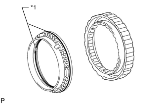
Text in Illustration *1 O-ring
-
Coat 2 new O-rings with ATF and install them to the No. 3 brake piston.
-
Press the No. 3 brake piston into the No. 3 brake cylinder with both hands.
Note
Be careful not to damage the O-rings.
-
Using SST and a press, compress the No. 3 brake piston return spring sub-assembly and install the snap ring with a screwdriver.
- SST
- 09380-60011 ( 09381-06020, 09381-06040, 09381-06060, 09381-06100, 09381-06110 )
Note
Be sure the end gap of the snap ring is not aligned with the No. 3 brake piston return spring sub-assembly claw.
-
-
INSTALL NO. 3 BRAKE CYLINDER WITH NO. 3 BRAKE PISTON AND NO. 3 BRAKE PISTON RETURN SPRING SUB-ASSEMBLY
-
Install the No. 3 brake cylinder together with the No. 3 brake piston and No. 3 brake piston return spring sub-assembly to the transmission case.
Note
-
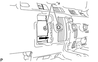
Align the oil holes of the No. 3 brake cylinder and transmission case as shown in the illustration.
-
Make sure the No. 3 brake piston and cylinder are securely inserted into the transmission case.
Text in Illustration *a Oil Hole -
-
-
INSTALL NO. 3 BRAKE PISTON HOLE SNAP RING
-
Using SST, install the No. 3 brake piston hole snap ring.
- SST
- 09350-30020 ( 09350-07060 )
-
-
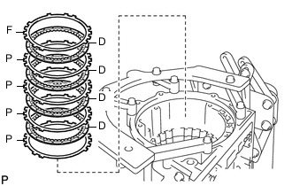
INSTALL NO. 3 BRAKE DISC SET
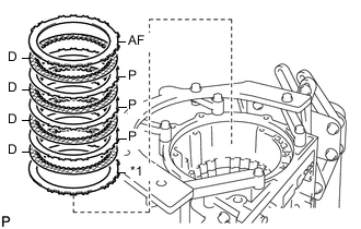
*1 OF
-
Install the ''O'' mark flange, 4 No. 3 brake discs, 3 plates and ''A'' mark flange to the transmission case.
Install in order OF - D - P - D - P - D - P - D - AF Tech Tips
OF = ''O'' mark flange
P = Plate
D = No. 3 brake disc
AF = ''A'' mark flange
Note
Before assembling new discs, soak them in ATF for at least 2 hours.
-
-
INSTALL NO. 3 BRAKE SNAP RING
-
Using a screwdriver, install the No. 3 brake snap ring.
Note
Be careful not to damage the transmission case.
Tech Tips
Wrap the tip of the screwdriver with protective tape before use.
-
-
INSTALL DIRECT CLUTCH PISTON SUB-ASSEMBLY
-
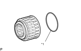
Text in Illustration *1 O-ring Coat 2 new O-rings with ATF and install them to the direct clutch piston sub-assembly.
-
Install the direct clutch return spring sub-assembly and No. 2 clutch balancer to the direct clutch piston sub-assembly.
-
Press the direct clutch piston sub-assembly together with the direct clutch return spring sub-assembly and No. 2 clutch balancer into the clutch drum with both hands.
Note
Be careful not to damage the O-ring.
-
Place SST on the direct clutch balancer and compress the direct clutch return spring sub-assembly with a press.
- SST
- 09350-30020 ( 09350-07070 )
- 09380-60011 ( 09381-06030, 09381-06040, 09381-06080 )
Note
Stop pressing when the spring sheet is lowered to a position 1 to 2 mm (0.0394 to 0.0787 in.) from the snap ring groove to prevent the spring sheet from being deformed.
-
Using SST, install the snap ring.
- SST
- 09350-30020 ( 09350-07070 )
Note
Do not expand the snap ring excessively.
-
Text in Illustration *a Stopper Set the end gap of the snap ring in the balancer as shown in the illustration.
Note
Be sure the end gap of the snap ring is not aligned with the spring retainer claw.
-
-
INSTALL DIRECT CLUTCH DISC SET
-
Place the oil pump assembly onto the torque converter assembly, and then place the clutch drum onto the oil pump assembly.
-
Install the 6 plates, 6 direct clutch discs and direct clutch flange to the clutch drum.
Install in order P - D - P - D - P - D - P - D - P - D - P - D - F Tech Tips
P = Plate
D = Direct clutch disc
F = Direct clutch flange
Note
Before assembling new direct clutch discs, soak them in ATF for at least 2 hours.
-
Using a screwdriver, install the snap ring to the clutch drum.
Note
Be careful not to damage the clutch drum.
Tech Tips
Wrap the tip of the screwdriver with protective tape before use.
-
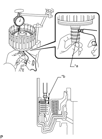
Using a dial indicator, measure the moving distance (A) of the direct clutch flange at both ends across the diameter while blowing compressed air (392 kPa, 2.0 kgf/cm2, 57 psi) into the oil hole as shown in the illustration. Then choose from the 9 flange thicknesses in the table so that the measured value is within the standard range.
Standard moving distance (A) 0.58 to 0.88 mm (0.0229 to 0.0346 in.) 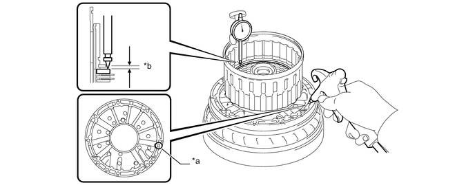
Text in Illustration *a Oil Hole *b Distance (A) Flange Thickness Mark Thickness 0 3.45 to 3.55 mm (0.136 to 0.139 in.) 1 3.55 to 3.65 mm (0.140 to 0.143 in.) 2 3.65 to 3.75 mm (0.144 to 0.147 in.) 3 3.75 to 3.85 mm (0.148 to 0.151 in.) 4 3.85 to 3.95 mm (0.152 to 0.155 in.) 5 3.95 to 4.05 mm (0.156 to 0.159 in.) 6 4.05 to 4.15 mm (0.160 to 0.163 in.) 7 4.15 to 4.25 mm (0.164 to 0.167 in.) 8 4.25 to 4.35 mm (0.168 to 0.171 in.) A 4.35 to 4.45 mm (0.172 to 0.175 in.) -
Temporarily remove the snap ring, install the selected direct clutch flange and reinstall the snap ring.
-
-
INSTALL REVERSE CLUTCH PISTON SUB-ASSEMBLY
-
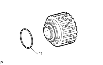
Text in Illustration *1 O-ring Coat a new O-ring with ATF and install it to the clutch drum.
-
Text in Illustration *1 O-ring Coat a new O-ring with ATF and install it to the reverse clutch piston sub-assembly.
-
Insert the clutch drum into the reverse clutch piston sub-assembly with both hands.
Note
-
Be careful not to damage the O-ring.
-
Make sure to align the holes of the reverse clutch piston with those of the clutch drum as shown in the illustration.
-
Make sure to align the protrusions of the reverse clutch piston with the cutout of the clutch drum.
-
-
-
INSTALL NO. 3 CLUTCH BALANCER
-
Text in Illustration *1 O-ring Coat a new O-ring with ATF and install it to the reverse clutch piston.
-
Install the reverse clutch return spring sub-assembly and No. 3 clutch balancer to the reverse clutch piston sub-assembly.
-
Place SST on the No. 3 clutch balancer and compress the clutch balancer with a press.
- SST
- 09380-60011 ( 09381-06020, 09381-06030, 09381-06040, 09381-06050, 09381-06070, 09381-06080 )
Note
Stop pressing when the spring sheet is lowered to a position 1 to 2 mm (0.0394 to 0.0787 in.) from the snap ring groove to prevent the spring sheet from being deformed.
-
Using SST, install the snap ring.
- SST
- 09350-30020 ( 09350-07070 )
Note
Do not expand the snap ring excessively.
-
Set the end gap of the snap ring in the reverse clutch piston sub-assembly as shown in the illustration.
Note
Be sure the end gap of the snap ring is not aligned with the spring retainer claw.
-
-
SELECT REVERSE CLUTCH FLANGE
-
Text in Illustration *a Protective Tape Using a screwdriver, install the snap ring to the clutch drum.
Note
-
Be careful not to damage the clutch drum.
-
Make sure to install the direct clutch and reverse clutch snap rings so that their openings face opposite directions.
Tech Tips
Wrap the tip of the screwdriver with protective tape before use.
-
-
*1 S/F Install the flange, 4 rear clutch discs, 3 plates, selected reverse clutch flange, cushion plate and reverse clutch reaction sleeve to the clutch drum.
Install in order F - D - P - D - P - D - P - D - S/F - C Tech Tips
F = Flange
D = Rear clutch disc
P = Plate
S/F = Selected reverse clutch flange
C = Cushion plate
-
Using a screwdriver, install the snap ring.
-
Using a dial indicator, measure the moving distance (A minus B) of the top surface of the reverse clutch piston (A) and cushion plate (B) at both ends across the diameter while blowing compressed air (392 kPa, 2.0 kgf/cm2, 57 psi) into the oil hole as shown in the illustration. Then choose from the 12 flange thicknesses in the table so that the measured value is within the standard range.
Standard moving distance (A minus B) 0.46 to 0.76 mm (0.0182 to 0.0299 in.) Text in Illustration *a Oil Hole *b Distance (A) *c Distance (B) - - Flange Thickness Mark Thickness 0 2.35 to 2.45 mm (0.0926 to 0.0964 in.) 1 2.45 to 2.55 mm (0.0965 to 0.100 in.) 2 2.55 to 2.65 mm (0.101 to 0.104 in.) 3 2.65 to 2.75 mm (0.105 to 0.108 in.) 4 2.75 to 2.85 mm (0.109 to 0.112 in.) 5 2.85 to 2.95 mm (0.113 to 0.116 in.) 6 2.95 to 3.05 mm (0.117 to 0.120 in.) 7 3.05 to 3.15 mm (0.121 to 0.124 in.) 8 3.15 to 3.25 mm (0.125 to 0.127 in.) A 3.25 to 3.35 mm (0.128 to 0.131 in.) B 3.35 to 3.45 mm (0.132 to 0.135 in.) C 3.45 to 3.55 mm (0.136 to 0.139 in.) -
Remove the snap ring, reverse clutch reaction sleeve and rear clutch disc set from the clutch drum.
-
-
INSTALL FORWARD CLUTCH PISTON SUB-ASSEMBLY
-
Text in Illustration *1 O-ring Coat a new O-ring with ATF and install it to the input shaft sub-assembly.
-
Install the forward clutch piston sub-assembly to the input shaft sub-assembly.
-
-
INSTALL COAST CLUTCH PISTON
-
Install the coast clutch piston to the input shaft sub-assembly.
-
Text in Illustration *1 O-ring Coat a new O-ring with ATF and install it to the No. 1 clutch balancer.
-
Install the forward clutch return spring and No. 1 clutch balancer to the input shaft.
Note
Be careful not to damage the O-rings.
-
Place SST on the No. 1 clutch balancer and compress the forward clutch return spring with a press.
- SST
- 09350-30020 ( 09350-07040 )
Note
Stop pressing when the spring sheet is lowered to a position 1 to 2 mm (0.0394 to 0.0787 in.) from the snap ring groove to prevent the spring sheet from being deformed.
-
Using SST, install the snap ring.
- SST
- 09350-30020 ( 09350-07070 )
Note
Do not expand the snap ring excessively.
-
Text in Illustration *a Correct *b Incorrect Set the end gap of the snap ring in the balancer as shown in the illustration.
Note
Be sure the end gap of the snap ring is not aligned with the spring retainer claw.
-
-
INSTALL COAST CLUTCH DISC SET
-
Install the 5 plates, 5 coast clutch discs and coast clutch flange.
Install in order P - D - P - D - P - D - P - D - P - D - F Tech Tips
P = Plate
D = Coast clutch disc
F = Coast clutch flange
Note
Before assembling new discs, soak them in ATF for at least 2 hours.
-
Text in Illustration *a Protective Tape Temporarily install the snap ring.
Note
Be careful not to damage the forward clutch piston sub-assembly.
Tech Tips
Wrap the tip of the screwdriver with protective tape before use.
-
Text in Illustration *a Oil Hole *b Distance (A) Using a dial indicator, measure the moving distance (A) of the coast clutch flange at both ends across the diameter while blowing compressed air (196 kPa, 2.0 kgf/cm2, 28 psi) into the oil hole as shown in the illustration. Then choose from the 11 flange thicknesses in the table so that the measured value is within the standard range.
Standard moving distance (A) 0.51 to 0.81 mm (0.0201 to 0.0318 in.) Flange Thickness Mark Thickness 0 2.95 to 3.05 mm (0.117 to 0.120 in.) 1 3.05 to 3.15 mm (0.121 to 0.124 in.) 2 3.15 to 3.25 mm (0.125 to 0.127 in.) 3 3.25 to 3.35 mm (0.128 to 0.131 in.) 4 3.35 to 3.45 mm (0.132 to 0.135 in.) 5 3.45 to 3.55 mm (0.136 to 0.139 in.) 6 3.55 to 3.65 mm (0.140 to 0.143 in.) 7 3.65 to 3.75 mm (0.144 to 0.147 in.) 8 3.75 to 3.85 mm (0.148 to 0.151 in.) A 3.85 to 3.95 mm (0.152 to 0.155 in.) B 3.95 to 4.05 mm (0.156 to 0.159 in.) -
Temporarily remove the snap ring, install the selected coast clutch flange and reinstall the snap ring.
Note
Be careful not to damage the forward clutch piston sub-assembly.
Tech Tips
Wrap the tip of the screwdriver with protective tape before use.
-
-
INSTALL FORWARD MULTIPLE DISC CLUTCH DISC SET
-
Install the cushion plate, 6 plates, 6 forward multiple disc clutch discs and flange to the input shaft.
Install in order C - P - D - P - D - P - D - P - D - P - D - P - D - F Tech Tips
C = Cushion plate
P = Plate
D = Forward multiple disc clutch disc
F = Flange
Note
Before assembling new forward multiple disc clutch discs, soak them in ATF for at least 2 hours.
-
Text in Illustration *a Protective Tape Temporarily install the snap ring.
Note
Be careful not to damage the forward clutch piston sub-assembly.
Tech Tips
Wrap the tip of the screwdriver with protective tape before use.
-
Text in Illustration *a Oil Hole *b Distance (A) Using a dial indicator, measure the moving distance (A) of the clutch flange at both ends across the diameter while blowing compressed air (196 kPa, 2.0 kgf/cm2, 28 psi) into the oil hole as shown in the illustration. Then choose from the 12 flange thicknesses in the table so that the measured value is within the standard range.
Standard moving distance (A) 0.85 to 1.15 mm (0.0335 to 0.0452 in.) Flange Thickness Mark Thickness 0 2.95 to 3.05 mm (0.117 to 0.120 in.) 1 3.05 to 3.15 mm (0.121 to 0.124 in.) 2 3.15 to 3.25 mm (0.125 to 0.127 in.) 3 3.25 to 3.35 mm (0.128 to 0.131 in.) 4 3.35 to 3.45 mm (0.132 to 0.135 in.) 5 3.45 to 3.55 mm (0.136 to 0.139 in.) 6 3.55 to 3.65 mm (0.140 to 0.143 in.) 7 3.65 to 3.75 mm (0.144 to 0.147 in.) 8 3.75 to 3.85 mm (0.148 to 0.151 in.) A 3.85 to 3.95 mm (0.152 to 0.155 in.) B 3.95 to 4.05 mm (0.156 to 0.159 in.) C 4.05 to 4.15 mm (0.160 to 0.163 in.) -
Temporarily remove the snap ring, install the selected flange and reinstall the snap ring.
Note
Be careful not to damage the forward clutch piston sub-assembly.
Tech Tips
Wrap the tip of the screwdriver with protective tape before use.
-
-
INSTALL NO. 4 1-WAY CLUTCH ASSEMBLY
-
Install the No. 2 clutch hub thrust washer to the coast clutch hub.
Tech Tips
Use a small amount of MP grease to make the No. 2 clutch hub thrust washer stay securely in place.
-
Install the No. 4 1-way clutch assembly to the coast clutch hub.
-
-
INSPECT NO. 4 1-WAY CLUTCH ASSEMBLY
-
INSTALL COAST CLUTCH HUB SUB-ASSEMBLY WITH NO. 4 1-WAY CLUTCH ASSEMBLY
-
Text in Illustration *1 Bearing (C) *2 Race (C) *3 Bearing (D) Install the 2 thrust needle roller bearings, thrust bearing race and coast clutch hub with the No. 4 1-way clutch assembly to the input shaft.
Tech Tips
Use a small amount of MP grease to make the thrust needle roller bearings and thrust bearing race stay securely in place.
Bearing and Race Diameter Item Inside Outside Bearing (C) 21.05 to 21.30 mm (0.829 to 0.838 in.) 39.63 to 39.88 mm (1.561 to 1.570 in.) Race (C) 22.80 to 23.10 mm (0.898 to 0.909 in.) 44.50 to 44.75 mm (1.75 to 1.76 in.) Bearing (D) 39.45 to 39.70 mm (1.55 to 1.56 in.) 60.50 to 60.75 mm (2.38 to 2.39 in.)
-
-
INSTALL INPUT SHAFT OIL SEAL RING
-
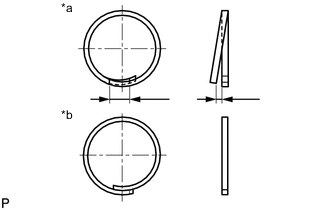
Text in Illustration *a Correct *b Incorrect Overlap the input shaft oil seal ring edges in the axial direction.
Note
-
Overlapping the input shaft oil seal ring edges in the axial direction prevents damage to the input shaft oil seal ring.
-
Do not overlap the input shaft oil seal ring edges in the radial direction, as this may damage the input shaft oil seal ring.
-
-
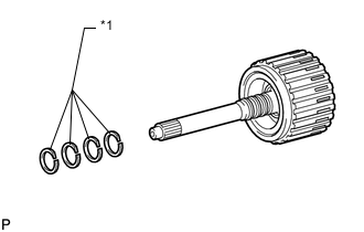
Text in Illustration *1 Input Shaft Oil Seal Ring Coat 4 new input shaft oil seal rings with ATF.
-
Squeeze the ends of the 4 input shaft oil seal rings together, and then install them to the input shaft sub-assembly groove.
Note
Do not excessively widen the input shaft oil seal rings.
Tech Tips
After installing the input shaft oil seal rings, check that they rotate smoothly.
-
-
INSTALL INPUT SHAFT SUB-ASSEMBLY
-
Install the input shaft sub-assembly to the clutch drum.
-
-
INSTALL FORWARD CLUTCH HUB SUB-ASSEMBLY
-
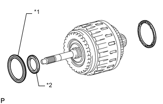
Install the No. 3 clutch hub thrust washer, forward clutch hub sub-assembly and thrust needle roller bearing to the clutch drum.
Note
Before installing the forward clutch hub sub-assembly, apply ATF to the sliding surfaces of the forward clutch hub bush. After the installation, check that the forward clutch hub sub-assembly rotates smoothly.
Tech Tips
Use a small amount of MP grease to make the thrust needle roller bearing and No. 3 clutch hub thrust washer stay securely in place.
Bearing Diameter Item Inside Outside Bearing (E) 46.45 to 46.70 mm (1.83 to 1.84 in.) 64.30 to 64.55 mm (2.53 to 2.54 in.)
-
-
INSTALL REVERSE CLUTCH HUB SUB-ASSEMBLY
-
Install the reverse clutch hub sub-assembly to the clutch drum.
Note
Before installing of the reverse clutch hub, apply ATF to the sliding surfaces of the reverse clutch hub bush. After the installation, check that the reverse clutch rotates smoothly.
-
-
INSTALL REAR CLUTCH DISC SET
-
Using a screwdriver, install the snap ring.
Note
Be careful not to damage the clutch drum.
Tech Tips
Wrap the tip of the screwdriver with protective tape before use.
-
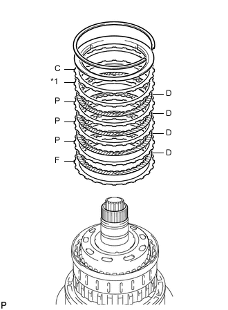
*1 S/F Install the flange, 4 discs, 3 plates, selected reverse clutch flange and reverse clutch reaction sleeve to the clutch drum.
Install in order F - D - P - D - P - D - P - D - S/F - C Tech Tips
F = Flange
D = Disc
P = Plate
S/F = Selected reverse clutch flange
C = Cushion plate
-
Using a screwdriver, install the snap ring to the clutch drum.
-
-
INSTALL NO. 2 1-WAY CLUTCH ASSEMBLY
-
Install the clutch drum thrust washer to the clutch drum.
Tech Tips
Use a small amount of MP grease to make the clutch drum thrust washer stay securely in place.
-
Install the 1-way clutch to the clutch drum.
-
-
INSPECT NO. 2 1-WAY CLUTCH ASSEMBLY
-
INSTALL CLUTCH DRUM AND INPUT SHAFT ASSEMBLY
-
Text in Illustration *1 Bearing (A) *2 Bearing (B) Install the 2 thrust needle roller bearings.
Tech Tips
Use a small amount of MP grease to make the thrust needle roller bearings stay securely in place.
Bearing Diameter Item Inside Outside Bearing (A) 71.96 to 72.26 mm (2.834 to 2.844 in.) 85.25 to 85.60 mm (3.357 to 3.370 in.) Bearing (B) 36.45 to 36.70 mm (1.44 to 1.45 in.) 52.10 to 52.60 mm (2.06 to 2.07 in.) -
Coat the clutch drum thrust washer with petroleum jelly and install it to the clutch drum and input shaft assembly.
-
Install the clutch drum and input shaft assembly to the transmission case.
-
-
INSTALL OIL PUMP ASSEMBLY
-
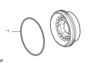
Text in Illustration *1 Race A *2 Race B *3 O-ring Coat a new O-ring with ATF and install it to the oil pump assembly.
-
Install the 2 thrust bearing races to the oil pump assembly.
Thrust Bearing Race Diameter Item Inside Outside Race (A) 74.26 to 74.56 mm (2.924 to 2.935 in.) 87.39 to 87.74 mm (3.441 to 3.454 in.) Race (B) 38.0 to 38.3 mm (1.497 to 1.507 in.) 53.9 to 54.1 mm (2.123 to 2.129 in.) -
Pass the input shaft sub-assembly through the center hole of the oil pump assembly, and align the bolt holes of the oil pump assembly with the transmission case.
-
Hold the input shaft sub-assembly and lightly press the oil pump assembly body to slide the oil seal rings into the overdrive direct clutch drum.
-
Apply seal packing to the flanges of the bolts.
Seal packing Toyota Genuine Seal Packing 1281, Three Bond 1281 or equivalent Note
Do not allow seal packing to contact the bolt threads.
-
Install the 10 bolts.
- Torque:
- 21 N*m { 214 kgf*cm, 15 ft.*lbf }
Note
During installation, do not allow oil to contact the bolts or the surface of the oil pump assembly body.
-
-
INSPECT INDIVIDUAL PISTON OPERATION
-
INSTALL MANUAL VALVE LEVER SHAFT OIL SEAL
-
Using SST, tap in 2 new manual valve lever shaft oil seals.
- SST
- 09350-30020 ( 09350-07110 )
-
Coat the lips of the manual valve lever shaft oil seals with MP grease.
-
-
INSTALL MANUAL VALVE LEVER SUB-ASSEMBLY
Text in Illustration *1 Spacer
-
Install a new spacer to the manual valve lever sub-assembly.
-
Push the manual valve lever shaft through the transmission case and install the manual valve lever sub-assembly to the manual valve lever shaft.
-
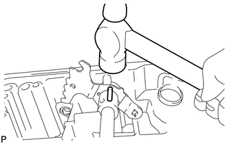
Using a hammer, tap in a new spring pin.
-
Align the manual valve lever indentation with the spacer hole and stake them together with a punch.
-
Check that the shaft rotates smoothly.
-
-
INSTALL PARKING LOCK PAWL
-
Install a new E-ring to the shaft.
-
Install the parking lock pawl, parking lock pawl shaft and spring.
-
-
INSTALL PARKING LOCK ROD SUB-ASSEMBLY
-
Connect the parking lock rod sub-assembly to the manual valve lever sub-assembly.
-
-
INSTALL PARKING LOCK PAWL BRACKET
-
Place the parking lock pawl bracket onto the transmission case and install the 3 bolts.
- Torque:
- 18 N*m { 184 kgf*cm, 13 ft.*lbf }
-
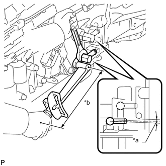
Text in Illustration *1 Parking Lock Pawl *2 Rear Planetary Gear Move the manual valve lever sub-assembly to the P position and confirm that the planetary ring gear is correctly locked by the lock pawl.
-
-
INSTALL B-1 ACCUMULATOR VALVE
-
Install the 2 springs and B-1 accumulator valve to the hole.
Spring Diameter Spring Free Length
Outer Diameter
Color B-1 Accumulator Valve Inner 44.98 mm (1.77 in.)
11.30 mm (0.445 in.)
Natural B-1 Accumulator Valve Outer 46.36 mm (1.83 in.)
17.10 mm (0.673 in.)
Natural
-
-
INSTALL C-3 ACCUMULATOR PISTON
-
Text in Illustration *1 O-ring Coat 2 new O-rings with ATF and install them to the C-3 accumulator piston.
-
Install the spring and C-3 accumulator piston to the hole.
Spring Diameter Spring Free Length
Outer Diameter
Color C-3 Accumulator Piston 76.65 mm (3.02 in.)
20.1 mm (0.791 in.)
White
-
-
INSTALL B-3 ACCUMULATOR PISTON
-
Text in Illustration *1 O-ring Coat 2 new O-rings with ATF and install them to the B-3 accumulator piston.
-
Install the spring and B-3 accumulator piston to the hole.
Spring Diameter Spring Free Length
Outer Diameter
Color B-3 Accumulator Piston 64.50 mm (2.54 in.)
19.5 mm (0.768 in.)
Orange
-
-
INSTALL C-2 ACCUMULATOR PISTON
-
Text in Illustration *1 O-ring Coat 2 new O-rings with ATF and install them to the C-2 accumulator piston.
-
Install the spring and C-2 accumulator piston to the hole.
Spring Diameter Spring Free Length
Outer Diameter
Color C-2 Accumulator Piston 68.0 mm (2.68 in.)
16.1 mm (0.633 in.)
Blue
-
-
INSTALL CHECK BALL BODY
-
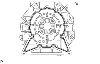
INSTALL BRAKE DRUM GASKET
-
Install 3 new brake drum gaskets.
-
-
INSTALL TRANSMISSION CASE GASKET
-
Install 3 new transmission case gaskets.
-
-
INSTALL TRANSMISSION VALVE BODY ASSEMBLY
-
INSTALL TRANSMISSION WIRE
-
CONNECT TRANSMISSION WIRE
-
INSTALL VALVE BODY OIL STRAINER ASSEMBLY
-
INSTALL AUTOMATIC TRANSMISSION OIL PAN SUB-ASSEMBLY
-
INSTALL TRANSFER CASE ADAPTER RADIAL BALL BEARING
-
Using SST and a press, press in the transfer case adapter radial ball bearing until it stops.
- SST
- 09950-60010 ( 09951-00650 )
- 09950-70010 ( 09951-07150 )
-
Using a screwdriver, install the snap ring.
-
-
INSTALL TRANSMISSION CASE ADAPTER OIL SEAL
-
Coat the lip of a new transmission case adapter oil seal with ATF.
-
Text in Illustration *a 0 to 1 mm Using SST and a hammer, tap in the transmission case adapter oil seal.
Standard depth 0 to 1 mm (0 to 0.0393 in.) - SST
- 09950-60010 ( 09951-00650 )
- 09950-70010 ( 09951-07150 )
-
-
INSTALL REAR TRANSFER ADAPTER
-
Clean the threads of the bolts and transmission case with non-residue solvent.
-
Text in Illustration *a Seal Packing Apply seal packing to the rear transfer adapter.
Seal packing Toyota Genuine Seal Packing 1281, Three Bond 1281 or equivalent Seal diameter 1.0 to 1.5 mm (0.0394 to 0.0590 in.) -
Install the rear transfer adapter with the 10 bolts.
- Torque:
- 34 N*m { 345 kgf*cm, 25 ft.*lbf }
-
-
INSTALL AUTOMATIC TRANSMISSION HOUSING
-
Clean the threads of the bolts and transmission case with non-residue solvent.
-
Install the automatic transmission housing with the 14 bolts.
- Torque:
- 34 N*m { 345 kgf*cm, 25 ft.*lbf }
-
-
INSTALL AUTOMATIC TRANSMISSION BREATHER TUBE
-
Coat a new O-ring with ATF and install it to the automatic transmission breather tube.
-
Install the automatic transmission breather tube with the 2 bolts.
- Torque:
- 5.4 N*m { 55 kgf*cm, 48 in.*lbf }
-
-
INSTALL OIL COOLER TUBE UNION
-
Coat 2 new O-rings with ATF and install them to the 2 oil cooler tube unions.
-
Text in Illustration *a -2 to 2° *b Torque Wrench Fulcrum Length Using a 19 mm union nut wrench, install the 2 oil cooler tube unions.
- Torque:
- Specified tightening torque
- 29 N*m { 296 kgf*cm, 21 ft.*lbf }
Tech Tips
-
Calculate the torque wrench reading when changing the fulcrum length of the torque wrench Click here.
-
When using a union nut wrench (fulcrum length of 30 mm (1.1811 in.)) + torque wrench (fulcrum length of 180 mm (7.0866 in.)): 25 N*m (254 kgf*cm, 18 ft.*lbf)
-
-
INSTALL SPEED SENSOR SP2
-
INSTALL SPEED SENSOR NT
-
INSTALL PARK/NEUTRAL POSITION SWITCH ASSEMBLY