AUTOMATIC TRANSMISSION UNIT INSPECTION

PROCEDURE
-
INSPECT AUTOMATIC TRANSMISSION OIL PAN SUB-ASSEMBLY
-
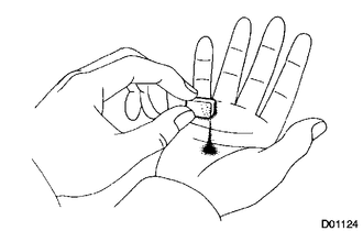
Remove the 4 transmission oil cleaner magnets, and use them to collect steel particles.
-
Carefully look at the foreign matter and particles in the automatic transmission oil pan sub-assembly and on the 4 transmission oil cleaner magnets to anticipate the type of wear you will find in the automatic transmission assembly.
Result Steel (magnetic) Bearing, gear and clutch plate wear Brass (non-magnetic) Bushing wear
-
-
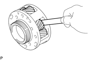
INSPECT NO. 2 1-WAY CLUTCH ASSEMBLY
-
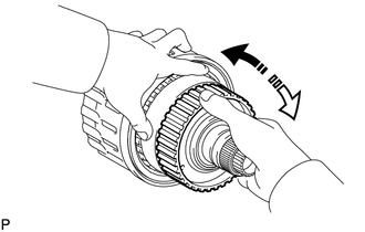
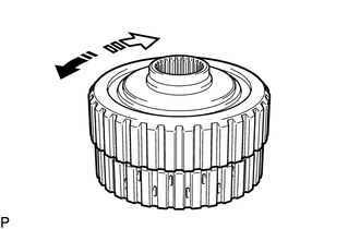
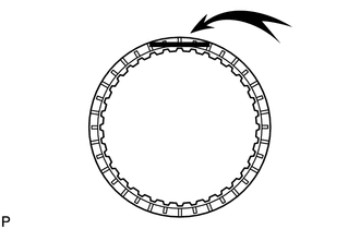
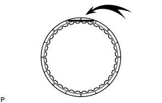
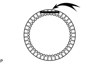
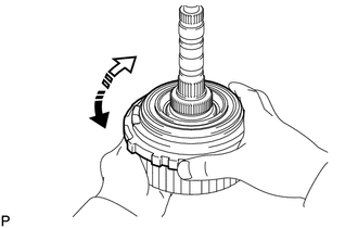
Hold the reverse clutch hub and turn the 1-way clutch assembly. Check that the 1-way clutch turns freely clockwise and locks when turned counterclockwise.
Text in Illustration 
Lock 
Free If the 1-way clutch assembly does not operate normally, replace it.
-
-
INSPECT REAR CLUTCH DISC
-
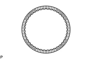
Replace all rear clutch discs if one of the following problems is present: 1) a rear clutch disc, plate or flange is worn or burnt, 2) the lining of a rear clutch disc is peeled off or discolored, or 3) grooves have even a little bit of damage.
Note
Before assembling new rear clutch discs, soak them in ATF for at least 2 hours.
If necessary, replace them.
-
-
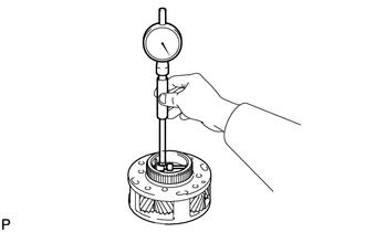
INSPECT REVERSE CLUTCH HUB SUB-ASSEMBLY
-
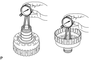
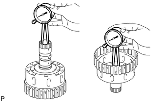
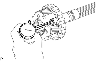
Using a dial indicator, measure the inside diameter of the reverse clutch hub bush.
Standard inside diameter 41.912 to 41.937 mm (1.6501 to 1.6510 in.)
-
If the inside diameter is more than the standard, replace the reverse clutch hub sub-assembly.
-
-
-
INSPECT FORWARD CLUTCH HUB SUB-ASSEMBLY
-
Using a dial indicator, measure the inside diameter of the forward clutch hub bush.
Standard inside diameter 30.200 to 30.225 mm (1.1890 to 1.1899 in.)
-
If the inside diameter is more than the standard, replace the forward clutch hub sub-assembly.
-
-
-
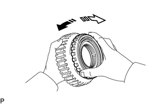
INSPECT NO. 4 1-WAY CLUTCH ASSEMBLY
-
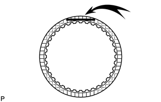
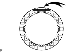
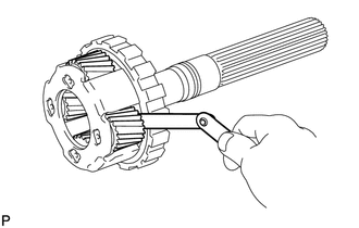
Hold the coast clutch hub and turn the No. 4 1-way clutch assembly. Check that the No. 4 1-way clutch turns freely clockwise and locks when turned counterclockwise.
Text in Illustration Lock Free If the No. 4 1-way clutch assembly does not operate normally, replace it.
-
-
INSPECT FORWARD MULTIPLE DISC CLUTCH DISC
-
Replace all forward multiple disc clutch discs if one of the following problems is present: 1) a forward multiple disc clutch disc, plate or flange is worn or burnt, 2) the lining of a forward multiple disc clutch disc is peeled off or discolored, or 3) grooves or printed numbers have even a little bit of damage.
Note
Before assembling new forward multiple disc clutch discs, soak them in ATF for at least 2 hours.
If necessary, replace them.
-
-
INSPECT COAST CLUTCH DISC
-
Replace all coast clutch discs if one of the following problems is present: 1) a coast clutch disc, plate or flange is worn or burnt, 2) the lining of a coast clutch disc is peeled off or discolored, or 3) grooves or printed numbers have even a little bit of damage.
Note
Before assembling new coast clutch discs, soak them in ATF for at least 2 hours.
If necessary, replace them.
-
-
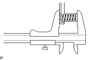
INSPECT FORWARD CLUTCH RETURN SPRING SUB-ASSEMBLY
-
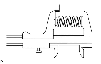
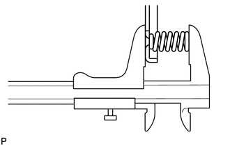
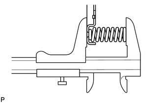
Using a vernier caliper, measure the free length of the spring together with the spring seat.
Standard free length 29.65 mm (1.17 in.) If the free length is not as specified, replace the forward clutch return spring sub-assembly.
-
-
INSPECT DIRECT CLUTCH DISC
-
Replace all direct clutch discs if one of the following problems is present: 1) a direct clutch disc, plate or flange is worn or burnt, 2) the lining of a direct clutch disc is peeled off or discolored, or 3) grooves or printed numbers have even a little bit of damage.
Note
Before assembling new direct clutch discs, soak them in ATF for at least 2 hours.
If necessary, replace them.
-
-
INSPECT REVERSE CLUTCH RETURN SPRING SUB-ASSEMBLY

-
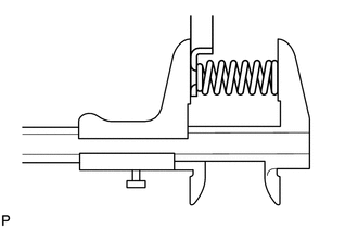
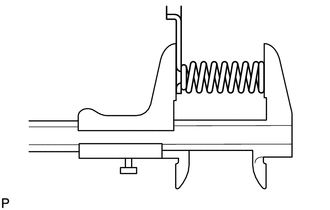
Using a vernier caliper, measure the free length of the spring together with the spring seat.
Standard free length 21.24 mm (0.836 in.) If the free length is not as specified, replace the reverse clutch return spring sub-assembly.
-
-
INSPECT DIRECT CLUTCH RETURN SPRING SUB-ASSEMBLY
-
Using a vernier caliper, measure the free length of the spring together with the spring seat.
Standard free length 19.46 mm (0.766 in.) If the free length is not as specified, replace the direct clutch return spring sub-assembly.
-
-
INSPECT NO. 3 BRAKE DISC
-
Replace all No. 3 brake discs if one of the following problems is present: 1) a No. 3 brake disc, plate or flange is worn or burnt, 2) the lining of a No. 3 brake disc is peeled off or discolored, or 3) grooves or printed numbers have even a little bit of damage.
Note
Before assembling new No. 3 brake discs, soak them in ATF for at least 2 hours.
If necessary, replace them.
-
-
INSPECT NO. 3 BRAKE PISTON RETURN SPRING SUB-ASSEMBLY
-
Using a vernier caliper, measure the free length of the spring together with the spring seat.
Standard free length 15.72 mm (0.619 in.) If the free length is not as specified, replace the No. 3 brake piston return spring sub-assembly.
-
-
INSPECT FRONT PLANETARY GEAR ASSEMBLY
-
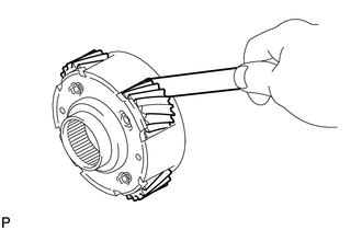
Using a feeler gauge, measure the front planetary pinion gear thrust clearance.
Standard clearance 0.2 to 0.6 mm (0.00788 to 0.0236 in.)
-
If the clearance is more than the standard, replace the front planetary gear assembly.
-
-
Using a cylinder gauge, measure the inside diameter of the front planetary gear bush.
Standard inside diameter 61.005 to 61.030 mm (2.4018 to 2.4027 in.)
-
If the inside diameter is more than the standard, replace the front planetary gear assembly.
-
-
-
INSPECT 1-WAY CLUTCH ASSEMBLY
-
Install the 1-way clutch assembly to the 1-way clutch inner race.
-
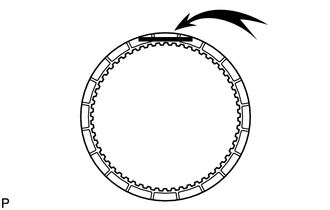
Hold the 1-way clutch inner race and turn the 1-way clutch assembly. Check that the 1-way clutch assembly turns freely counterclockwise and locks when turned clockwise.
Text in Illustration Free Lock If the 1-way clutch assembly does not operate normally, replace it.
-
Remove the 1-way clutch assembly from the 1-way clutch inner race.
-
-
INSPECT NO. 1 BRAKE DISC

-
Replace all No. 1 brake discs if one of the following problems is present: 1) a No. 1 brake disc, plate or flange is worn or burnt, 2) the lining of a No. 1 brake disc is peeled off or discolored, or 3) grooves or printed numbers have even a little bit of damage.
Note
Before assembling new No. 1 brake discs, soak them in ATF for at least 2 hours.
If necessary, replace them.
-
-
INSPECT BRAKE PISTON RETURN SPRING SUB-ASSEMBLY
-
Using a vernier caliper, measure the free length of the spring together with the spring seat.
Standard free length 17.05 mm (0.671 in.) If the free length is not as specified, replace the brake piston return spring sub-assembly.
-
-
INSPECT NO. 2 BRAKE DISC
-
Replace all No. 2 brake discs if one of the following problems is present: 1) a No. 2 brake disc, plate or flange is worn or burnt, 2) the lining of a No. 2 brake disc is peeled off or discolored, or 3) grooves or printed numbers have even a little bit of damage.
Note
Before assembling new No. 2 brake discs, soak them in ATF for at least 2 hours.
If necessary, replace them.
-
-
INSPECT NO. 2 BRAKE PISTON RETURN SPRING SUB-ASSEMBLY
-
Using a vernier caliper, measure the free length of the spring together with the spring seat.
Standard free length 22.66 mm (0.892 in.) If the free length is not as specified, replace the No. 2 brake piston return spring sub-assembly.
-
-
INSPECT CENTER PLANETARY GEAR ASSEMBLY
-
Using a feeler gauge, measure the center planetary pinion gear thrust clearance.
Standard clearance 0.20 to 0.60 mm (0.00788 to 0.0236 in.)
-
If the clearance is more than the standard, replace the center planetary gear assembly.
-
-
-
INSPECT NO. 3 1-WAY CLUTCH ASSEMBLY
-
Hold the rear planetary ring gear flange and turn the No. 3 1-way clutch assembly. Check that the No. 3 1-way clutch assembly turns freely counterclockwise and locks when turned clockwise.
Text in Illustration Free Lock If the No. 3 1-way clutch assembly does not operate normally, replace it.
-
-
INSPECT INTERMEDIATE SHAFT
-
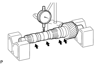
Using a dial indicator, check the intermediate shaft runout.
Standard runout 0.03 mm (0.00118 in.) If the runout is more than the standard, replace the intermediate shaft with a new one.
-
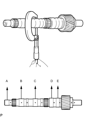
Using a micrometer, check the diameter of the intermediate shaft at the positions shown in the diagram.
Standard diameter A 19.963 to 19.976 mm (0.7860 to 0.7864 in.) B, C 30.150 to 30.163 mm (1.1871 to 1.1875 in.) D, E 36.404 to 36.420 mm (1.4333 to 1.4338 in.) If the diameter is less than the standard, replace the intermediate shaft with a new one.
-
-
INSPECT NO. 4 BRAKE DISC
-
Replace all No. 4 brake discs if one of the following problems is present: 1) a No. 4 brake disc, plate or flange is worn or burnt, 2) the lining of a No. 4 brake disc is peeled off or discolored, or 3) grooves or printed numbers have even a little bit of damage.
Note
Before assembling new No. 4 brake discs, soak them in ATF for at least 2 hours.
If necessary, replace them.
-
-
INSPECT REAR PLANETARY GEAR ASSEMBLY
-
Using a feeler gauge, measure the rear planetary pinion gear thrust clearance.
Standard clearance 0.2 to 0.6 mm (0.00788 to 0.0236 in.)
-
If the clearance is more than the standard, replace the rear planetary gear assembly.
-
-
Using a dial indicator, measure the inside diameter of the rear planetary gear bush.
Standard inside diameter 20.000 to 20.025 mm (0.7874 to 0.7883 in.)
-
If the inside diameter is more than the standard, replace the rear planetary gear assembly.
-
-
-
INSPECT 1ST AND REVERSE BRAKE RETURN SPRING SUB-ASSEMBLY
-
Using a vernier caliper, measure the free length of the spring together with the spring seat.
Standard free length 23.54 to 23.94 mm (0.927 to 0.942 in.) If the free length is not as specified, replace the 1st and reverse brake return spring sub-assembly.
-
-
INSPECT INDIVIDUAL PISTON OPERATION
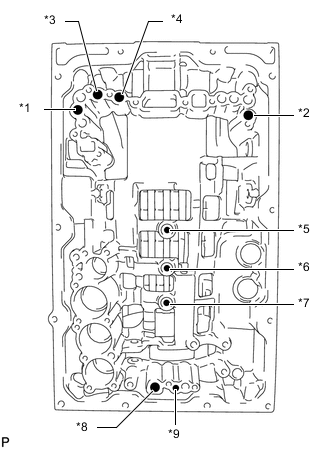
Text in Illustration *1 No. 2 Clutch *2 No. 3 Clutch *3 No. 4 Clutch *4 No. 1 Clutch *5 No. 3 Brake *6 No. 1 Brake *7 No. 2 Brake *8 No. 4 Brake (Out) *9 No. 4 Brake (In)
-
Check the operating sound while applying compressed air into the oil holes indicated in the illustration.
Tech Tips
When inspecting the direct clutch, check with the accumulator piston holes indicated in the illustration.
If there is no sound, disassemble and check the installation condition of the parts.
-