COMBINATION SWITCH INSPECTION
PROCEDURE
-
INSPECT INTEGRATION CONTROL AND PANEL ASSEMBLY
-
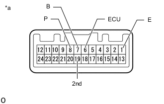
Text in Illustration *a Component without harness connected
(Integration Control and Panel Assembly)
Measure the resistance according to the value(s) in the table below.
Standard Resistance Tester Connection Switch Condition Specified Condition 8 (P) - 1 (E) SPORT S or SPORT S+ mode switch turned and held at SPORT S or SPORT S+ position Below 1 Ω SPORT S or SPORT S+ mode switch not turned 10 kΩ or higher 6 (ECU) - 1 (E) COMF or ECO mode switch turned and held at COMF or ECO position Below 1 Ω COMF or ECO mode switch not turned 10 kΩ or higher 19 (2nd) - 1 (E) Mode switch (ECT 2nd) on Below 1 Ω Mode switch (ECT 2nd) off 10 kΩ or higher 7 (B) - 1 (E) NORMAL mode switch pushed and held Below 1 Ω NORMAL mode switch not pushed 10 kΩ or higher If the result is not as specified, replace the integration control and panel assembly.
-