PARK / NEUTRAL POSITION SWITCH INSTALLATION
PROCEDURE
-
INSTALL PARK/NEUTRAL POSITION SWITCH ASSEMBLY
Tech Tips
Make sure that the manual valve lever shaft has not been rotated prior to installing the park/neutral position switch assembly as the detent spring may become detached from the manual valve lever shaft.
-
Clean the bolt and the bolt hole.
-
Apply adhesive to 2 or 3 threads on the end of the bolt.
Adhesive Toyota Genuine Adhesive 1344, Three Bond 1344 or equivalent -
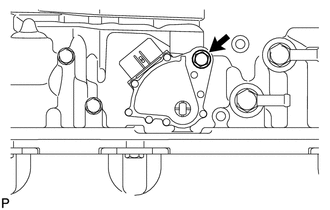
Temporarily install the park/neutral position switch assembly to the automatic transmission assembly with the bolt.
Tech Tips
Tighten the bolt to the specified torque when adjusting the park/neutral position switch assembly.
-
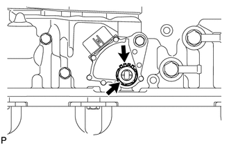
Install the lock washer and the lock nut to the park/neutral position switch assembly.
- Torque:
- 6.9 N*m { 70 kgf*cm, 61 in.*lbf }
-
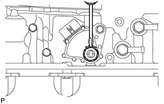
Temporarily install the transmission control shaft lever RH to the manual valve lever shaft with the spring washer and nut.
Tech Tips
Tighten the nut to the specified torque when adjusting the park/neutral position switch assembly.
-
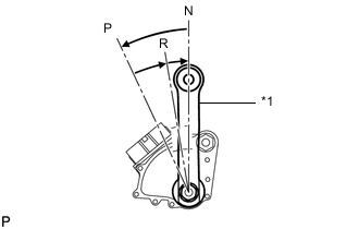
Text in Illustration *1 Transmission Control Shaft Lever RH Turn the transmission control shaft lever RH counterclockwise until it stops, then turn it clockwise 2 notches.
-
Remove the nut, spring washer and transmission control shaft lever RH from the manual valve lever shaft.
-
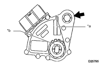
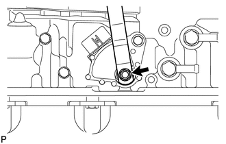
Text in Illustration *a Neutral Basic Line *b Groove Align the neutral basic line with the groove as shown in the illustration.
-
Hold the park/neutral position switch assembly in that position and tighten the bolt.
- Torque:
- 13 N*m { 130 kgf*cm, 9 ft.*lbf }
-
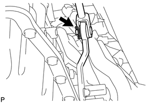
Using a screwdriver, bend down the tabs of the lock washer.
Tech Tips
Bend at least 2 of the lock washer tabs.
-
Install the transmission control shaft lever RH to the manual valve lever shaft with the spring washer and nut.
- Torque:
- 16 N*m { 160 kgf*cm, 12 ft.*lbf }
-
Connect the park/neutral position switch assembly connector.
-
-
CONNECT FLOOR SHIFT GEAR SHIFTING ROD SUB-ASSEMBLY
-
Connect the floor shift gear shifting rod sub-assembly to the transmission control shaft lever RH with the pin.
-
Install a new clip.
-
-
INSPECT SHIFT LEVER POSITION
-
INSPECT PARK/NEUTRAL POSITION SWITCH ASSEMBLY
-
INSTALL NO. 3 FRONT FLOOR HEAT INSULATOR
-
Install the No. 3 front floor heat insulator with the 4 nuts.
- Torque:
- 5.0 N*m { 51 kgf*cm, 44 in.*lbf }
-
-
INSTALL FRONT EXHAUST PIPE ASSEMBLY (w/ DPF)
-
INSPECT FOR EXHAUST GAS LEAK