TRANSMISSION WIRE INSTALLATION
PROCEDURE
-
INSTALL TRANSMISSION WIRE
-
Coat the 2 new O-rings with automatic transmission fluid.
-
Install the 2 O-rings to the No. 1 transmission wire and No. 2 transmission wire.
-
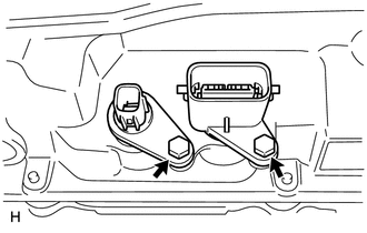
Install the No. 1 transmission wire and No. 2 transmission wire with the 2 bolts.
- Torque:
- 5.4 N*m { 55 kgf*cm, 48 in.*lbf }
Note
-
When reusing the transmission wire, inspect the O-ring.
-
Make sure that the O-ring is not cracked or jammed when installing the transmission wire.
-
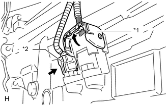
Connect the No. 2 transmission wire connector.
-
Connect the No. 1 transmission wire connector.
Text in Illustration *1 No. 1 Transmission Wire *2 No. 2 Transmission Wire Tech Tips
Push up the lever until the claw of the transmission wire connector makes a connection sound.
-
-
CONNECT TRANSMISSION WIRE
-
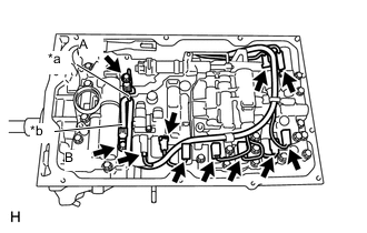
Text in Illustration *a Orange *b Blue Connect the 9 connectors to the solenoid valves.
-
Coat the 2 new O-rings with ATF and install them to the 2 ATF temperature sensors.
-
Connect the 2 ATF temperature sensors with the 2 temperature sensor clamps and 2 bolts.
- Torque:
- for bolt A
- 10 N*m { 102 kgf*cm, 7 ft.*lbf }
- for bolt B
- 11 N*m { 112 kgf*cm, 8 ft.*lbf }
Bolt Length Item Length Bolt A 12 mm (0.472 in.) Bolt B 36 mm (1.41 in.)
-
-
INSTALL VALVE BODY OIL STRAINER ASSEMBLY
-
Coat a new O-ring with ATF and install it to the valve body oil strainer assembly.
Note
Ensure that the O-ring is not twisted or pinched.
-
Install the valve body oil strainer assembly to the transmission valve body assembly with the 4 bolts.
- Torque:
- 10 N*m { 102 kgf*cm, 7 ft.*lbf }
-
-
INSTALL AUTOMATIC TRANSMISSION OIL PAN SUB-ASSEMBLY
-
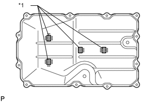
Text in Illustration *1 Transmission Oil Cleaner Magnet Install the 4 transmission oil cleaner magnets to the automatic transmission oil pan sub-assembly as shown in the illustration.
-
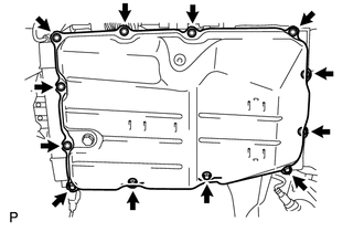
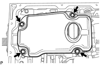
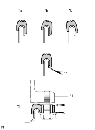
Text in Illustration *1 Automatic Transmission Case Sub-assembly *2 Sleeve *a Correct *b Incorrect *c Protrusion Install a new automatic transmission oil pan gasket and the automatic transmission oil pan sub-assembly with the 12 bolts.
- Torque:
- 7.4 N*m { 75 kgf*cm, 65 in.*lbf }
Note
-
Make sure that automatic transmission oil pan gasket seal surface and automatic transmission oil pan sub-assembly contact surface are free of oil and foreign matter.
-
Install the automatic transmission oil pan gasket so that there is no slack in the automatic transmission oil pan gasket, and the entire seal surface is level.
-
Make sure that the 12 protrusions are properly engaged to the automatic transmission oil pan sub-assembly.
-
When installing the automatic transmission oil pan sub-assembly, make sure that the automatic transmission oil pan gasket is not pinched between a sleeve and the seal surface of the automatic transmission case sub-assembly.
-
-
ADJUST AUTOMATIC TRANSMISSION FLUID
-
INSTALL OIL PAN PROTECTOR ASSEMBLY RH (w/ DPF)
-
INSTALL OIL PAN PROTECTOR ASSEMBLY LH (w/ DPF)
-
INSTALL OIL PAN PROTECTOR ASSEMBLY (w/o DPF)
-
INSTALL NO. 2 ENGINE UNDER COVER