DYNAMIC RADAR CRUISE CONTROL SYSTEM Distance Control Switch Circuit
DESCRIPTION
The driving support ECU assembly receives a lane departure alert main switch signal from the steering pad switch assembly and sends the signal to the forward recognition camera via CAN communication.
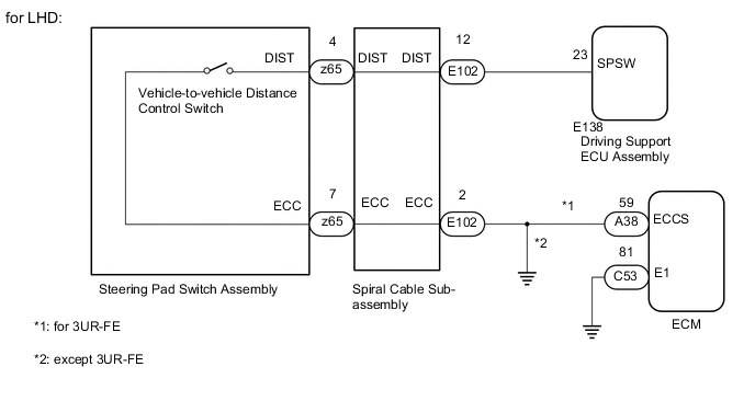
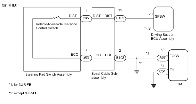
WIRING DIAGRAM
CAUTION / NOTICE / HINT
Note
-
The vehicle is equipped with a Supplemental Restraint System (SRS) which includes components such as airbags. Before servicing (including removal or installation of parts), be sure to read the precaution for Supplemental Restraint System Click here.
-
When replacing the driving support ECU assembly, always replace it with a new one. If a driving support ECU assembly which was installed to another vehicle is used, the information stored in the driving support ECU assembly will not match the information from the vehicle. As a result, a DTC may be stored.
PROCEDURE
-
INSPECT STEERING PAD SWITCH ASSEMBLY
-
Remove the steering pad switch assembly Click here.
-
Inspect the steering pad switch assembly Click here.
NG 
REPLACE STEERING PAD SWITCH ASSEMBLY Click here
OK 
-
-
INSPECT SPIRAL CABLE SUB-ASSEMBLY
-
Remove the spiral cable sub-assembly Click here.
-
Inspect the spiral cable sub-assembly Click here.
NG
REPLACE SPIRAL WITH SENSOR CABLE SUB-ASSEMBLY Click here
OK
-
-
CHECK HARNESS AND CONNECTOR (SPIRAL CABLE SUB-ASSEMBLY - DRIVING SUPPORT ECU ASSEMBLY)
-
Disconnect the E102 spiral cable sub-assembly connector.
-
Disconnect the E138 driving support ECU assembly connector.
-
Measure the resistance according to the value(s) in the table below.
Standard Resistance Tester Connection Condition Specified Condition E102-12 (DIST) - E138-23 (SPSW) Always Below 1 Ω E102-12 (DIST) or E138-23 (SPSW) - Body ground Always 10 kΩ or higher Result Result Proceed to OK (for 3UR-FE) A OK (except 3UR-FE) B NG C
B 
CHECK HARNESS AND CONNECTOR (SPIRAL CABLE SUB-ASSEMBLY - BODY GROUND) Click here
C
REPAIR OR REPLACE HARNESS OR CONNECTOR
A
-
-
CHECK HARNESS AND CONNECTOR (SPIRAL CABLE SUB-ASSEMBLY - ECM)
-
Disconnect the E102 spiral cable sub-assembly connector.
-
Disconnect the A38*1 or A87*2 ECM connector.
-
*1: for LHD
-
*2: for RHD
-
-
Measure the resistance according to the value(s) in the table below.
Standard Resistance Tester Connection Condition Specified Condition E102-2 (ECC) - A38-59 (ECCS)*1 Always Below 1 Ω E102-2 (ECC) - A87-59 (ECCS)*2
NG
REPAIR OR REPLACE HARNESS OR CONNECTOR
OK
-
-
CHECK HARNESS AND CONNECTOR (ECM- BODY GROUND)
-
Disconnect the C53*1 or A54*2 ECM connector.
-
*1: for LHD
-
*2: for RHD
-
-
Measure the resistance according to the value(s) in the table below.
Standard Resistance Tester Connection Condition Specified Condition C53-81 (E1) - Body ground*1 Always Below 1 Ω A54-81 (E1) - Body ground*2
OK
PROCEED TO NEXT SUSPECTED AREA SHOWN IN PROBLEM SYMPTOMS TABLE Click here
NG
REPAIR OR REPLACE HARNESS OR CONNECTOR
-
-
CHECK HARNESS AND CONNECTOR (SPIRAL CABLE SUB-ASSEMBLY - BODY GROUND)
-
Disconnect the E102 spiral cable sub-assembly connector.
-
Measure the resistance according to the value(s) in the table below.
Standard Resistance Tester Connection Condition Specified Condition E102-2 (ECC) - Body ground Always Below 1 Ω
OK
PROCEED TO NEXT SUSPECTED AREA SHOWN IN PROBLEM SYMPTOMS TABLE Click here
NG
REPAIR OR REPLACE HARNESS OR CONNECTOR
-