DYNAMIC RADAR CRUISE CONTROL SYSTEM, Diagnostic DTC:P0571/76
| DTC Code | DTC Name |
|---|---|
| P0571/76 | Brake Switch "A" Circuit |
DESCRIPTION
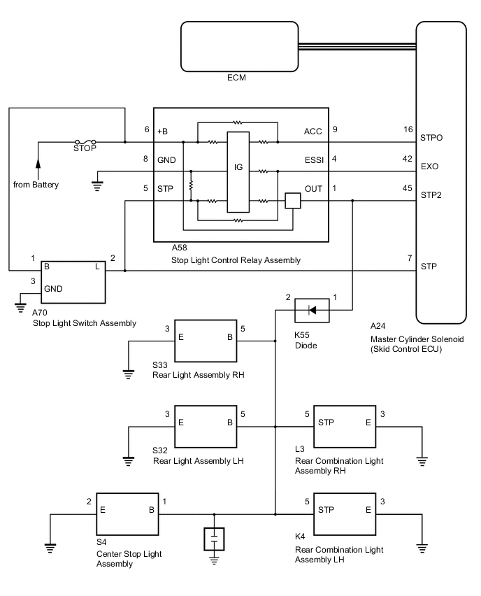
The ECM receives the brake demand signal from the driving support ECU assembly and transmits it to the skid control ECU (master cylinder solenoid).
The skid control ECU (master cylinder solenoid) receives a signal from the ECM and operates the skid control ECU (master cylinder solenoid).
The skid control ECU (master cylinder solenoid) operates simultaneously the stop light control relay assembly and illuminates the stop rights.
| DTC No. | DTC Detection Condition | Trouble Area |
|---|---|---|
| P0571/76 | While the dynamic radar cruise control system is operating (vehicle-to-vehicle distance control mode), the ECM detects the stop light control relay signal from the skid control ECU (master cylinder solenoid) for approximately 0.2 seconds or more. |
|
WIRING DIAGRAM
CAUTION / NOTICE / HINT
Note
-
Inspect the fuses for circuits related to this system before performing the following procedure.
-
After replacing the master cylinder solenoid, perform zero point calibration and store the system information Click here.
-
When the start function does not operate, check the Entry and Start System (for start function) Click here.
PROCEDURE
-
CHECK STOP LIGHT OPERATION
-
Check that the stop lights come on when the brake pedal is depressed and go off when the brake pedal is released.
OK: Condition Illumination Condition Brake pedal depressed On Brake pedal released Off
NG 
GO TO LIGHTING SYSTEM Click here
OK 
-
-
CHECK HARNESS AND CONNECTOR (STPO TERMINAL VOLTAGE)
-
Turn the engine switch off.
-
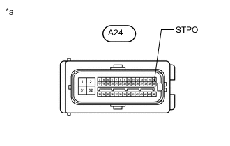
Text in Illustration *a Front view of wire harness connector (to Skid Control ECU [Master Cylinder Solenoid]) Disconnect the skid control ECU (master cylinder solenoid) connector.
-
Measure the voltage according to the value(s) in the table below.
Standard Voltage Tester Connection Condition Specified Condition A24-16 (STPO) - Body ground Engine switch on (IG) 11 to 14 V
NG 
CHECK HARNESS AND CONNECTOR (STOP LIGHT CONTROL RELAY ASSEMBLY - SKID CONTROL ECU [MASTER CYLINDER SOLENOID]) Click here
OK
-
-
PERFORM ACTIVE TEST USING ACTIVE TEST USING GTS (STOP LIGHT RELAY)
-
Enter the following menus: Chassis / ABS/VSC/TRC / Active Test.
-
Perform "Active Test" according to the display on the GTS.
ABS/VSC/TRC Tester Display Test Part Control Range Diagnostic Note Stop Light Relay Stop light control relay assembly Relay ON/OFF Observe the stop light (the stop lights do not come on for 2 to 5 seconds) -
Enter the following menus: Chassis / ABS/VSC/TRC / Data List.
-
Check the stop light switch assembly (stop light control relay assembly) operation using the Data List and stop light operation by performing an Active Test.
ABS/VSC/TRC Tester Display Measurement Item/Range Normal Condition Diagnostic Note Stop Light Relay Output Stop light control relay assembly Stop light control relay assembly/ON or OFF ON: Relay output on (Stop light on)
OFF: Relay output off (Stop light off)
- Result Result Proceed to When Active Test performed, Data List item not changes between ON and OFF A When Active Test performed, Data List item changes between ON and OFF and stop lights turn on and off B
B
CHECK HARNESS AND CONNECTOR (STP2 TERMINAL VOLTAGE) Click here
A
-
-
INSPECT SKID CONTROL ECU (MASTER CYLINDER SOLENOID)
-
Enter the following menus: Chassis / ABS/VSC/TRC / Active Test.
-
Perform "Active Test" according to the display on the GTS.
ABS/VSC/TRC Tester Display Test Part Control Range Diagnostic Note Stop Light Relay Stop light control relay assembly Relay ON/OFF Observe the stop light (the stop lights do not come on for 2 to 5 seconds) -
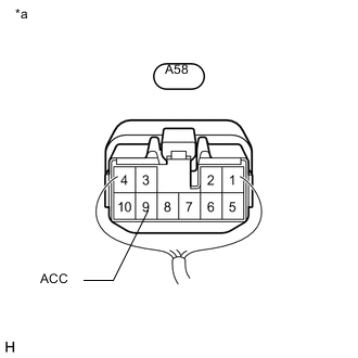
Text in Illustration *a Component with harness connected
(Stop Light Control Relay Assembly)
Measure the voltage according to the value(s) in the table below.
Standard Voltage Tester Connection Condition Specified Condition A58-9 (ACC) - Body ground Active test is ON Below 1.5 V Result Result Proceed to OK A NG (for LHD) B NG (for RHD) C
B
REPLACE SKID CONTROL ECU (MASTER CYLINDER SOLENOID) Click here
C
REPLACE SKID CONTROL ECU (MASTER CYLINDER SOLENOID) Click here
A
-
-
REPLACE STOP LIGHT CONTROL RELAY ASSEMBLY
-
Replace the stop light control relay assembly.
for LHD: Click here
for RHD: Click here
NEXT
-
-
CHECK FOR DTC
-
Enter the following menus: Chassis / ABS/VSC/TRC / Active Test.
Tech Tips
If the detection conditions are not met, the system cannot detect the malfunction.
-
Using the GTS, perform the Active Test "Stop Light Relay" with the ignition switch to ON.
-
-
Perform "Active Test" according to the display on the GTS.
ABS/VSC/TRC Tester Display Test Part Control Range Diagnostic Note Stop Light Relay Stop light control relay assembly Relay ON/OFF Observe the stop light (the stop lights do not come on for 2 to 5 seconds) EBS Relay Stop light control relay assembly
(Emergency brake signal)
Relay ON/OFF - -
Enter the following menus: Chassis / ABS/VSC/TRC / Data List.
-
Check the stop light switch assembly (stop light control relay assembly) operation using the Data List and stop light operation by performing an Active Test.
ABS/VSC/TRC Tester Display Measurement Item/Range Normal Condition Diagnostic Note Stop Light Relay Output Stop light control relay assembly Stop light control relay assembly/ON or OFF ON: Relay output on (Stop light on)
OFF: Relay output off (Stop light off)
- EBS Relay Stop light control relay assembly (Emergency brake signal)/ON or OFF ON: Relay on
OFF: Relay off
- -
Clear the DTCs Click here.
-
Check for DTCs Click here.
Result Result Proceed to DTC C1380 is output A DTC C1380 is not output B
A
GO TO DTC C1380 Click here
B
END (STOP LIGHT CONTROL RELAY ASSEMBLY WAS DEFECTIVE)
-
-
CHECK HARNESS AND CONNECTOR (STP2 TERMINAL VOLTAGE)
-
Turn the engine switch off.
-
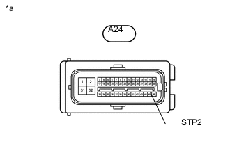
Text in Illustration *a Front view of wire harness connector
(to Skid Control ECU [Master Cylinder Solenoid])
Disconnect the skid control ECU (master cylinder solenoid ) connector.
-
Measure the voltage according to the value(s) in the table below.
Standard Voltage Tester Connection Condition Specified Condition A24-45 (STP2) - Body ground Brake pedal depressed 11 to 14 V
NG
REPAIR OR REPLACE HARNESS OR CONNECTOR
OK
-
-
REPLACE SKID CONTROL ECU (MASTER CYLINDER SOLENOID)
-
Replace the skid control ECU (master cylinder solenoid).
for LHD: Click here
for RHD: Click here
NEXT
-
-
CHECK FOR DTC
-
Enter the following menus: Chassis / ABS/VSC/TRC / Active Test.
Tech Tips
If the detection conditions are not met, the system cannot detect the malfunction.
-
Using the GTS, perform the Active Test "Stop Light Relay" with the ignition switch to ON.
-
-
Perform "Active Test" according to the display on the GTS.
ABS/VSC/TRC Tester Display Test Part Control Range Diagnostic Note Stop Light Relay Stop lights ON / OFF Test possible at vehicle speed of 0 km/h (0 mph) EBS Relay Stop light control relay
(Emergency brake signal)
ON / OFF - -
Enter the following menus: Chassis / ABS/VSC/TRC / Data List.
-
Check the stop light switch assembly (stop light control relay assembly) operation using the Data List and stop light operation by performing an Active Test.
ABS/VSC/TRC Tester Display Measurement Item/Range Normal Condition Diagnostic Note Stop Light Relay Output STOP terminal output condition/ON or OFF ON: Output
ON: Not output
- EBS Relay Stop light control relay (Emergency brake signal)/ON or OFF ON: Relay on
OFF: Relay off
- -
Clear the DTCs Click here.
-
Check for DTCs Click here.
Result Result Proceed to DTC C1380 is output A DTC C1380 is not output B
A
GO TO DTC C1380 Click here
B
END (STOP LIGHT CONTROL RELAY ASSEMBLY WAS DEFECTIVE)
-
-
CHECK HARNESS AND CONNECTOR (STOP LIGHT CONTROL RELAY ASSEMBLY - SKID CONTROL ECU [MASTER CYLINDER SOLENOID])
-
Disconnect the A58 stop light control relay assembly connector.
-
Disconnect the A24 skid control ECU (master cylinder solenoid) connector.
-
Measure the resistance according to the value(s) in the table below.
Standard Resistance Tester Connection Condition Specified Condition A58-9 (ACC) - A24-16 (STPO) Always Below 1 Ω A58-9 (ACC) or A24-16 (STPO) - Body ground Always 10 kΩ or higher
NG
REPAIR OR REPLACE HARNESS OR CONNECTOR
OK
-
-
REPLACE STOP LIGHT CONTROL RELAY ASSEMBLY
-
Replace the stop light control relay assembly.
for LHD: Click here
for RHD: Click here
NEXT
-
-
CHECK FOR DTC
-
Enter the following menus: Chassis / ABS/VSC/TRC / Active Test.
Tech Tips
If the detection conditions are not met, the system cannot detect the malfunction.
-
Using the GTS, perform the Active Test "Stop Light Relay" with the ignition switch to ON.
-
-
Perform "Active Test" according to the display on the GTS.
ABS/VSC/TRC Tester Display Test Part Control Range Diagnostic Note Stop Light Relay Stop lights ON / OFF Test possible at vehicle speed of 0 km/h (0 mph) EBS Relay Stop light control relay
(Emergency brake signal)
ON / OFF - -
Enter the following menus: Chassis / ABS/VSC/TRC / Data List.
-
Check the stop light switch assembly (stop light control relay assembly) operation using the Data List and stop light operation by performing an Active Test.
ABS/VSC/TRC Tester Display Measurement Item/Range Normal Condition Diagnostic Note Stop Light Relay Output STOP terminal output condition/ON or OFF ON: Output
ON: Not output
- EBS Relay Stop light control relay (Emergency brake signal)/ON or OFF ON: Relay on
OFF: Relay off
- -
Clear the DTCs Click here.
-
Check for DTCs Click here.
Result Result Proceed to DTC C1380 is output A DTC C1380 is not output B
A
GO TO DTC C1380 Click here
B
END (STOP LIGHT CONTROL RELAY ASSEMBLY WAS DEFECTIVE)
-