STARTER REASSEMBLY
PROCEDURE
-
INSTALL STARTER CLUTCH SUB-ASSEMBLY
-
Apply high-temperature grease to the parts indicated by the arrows in the illustration.
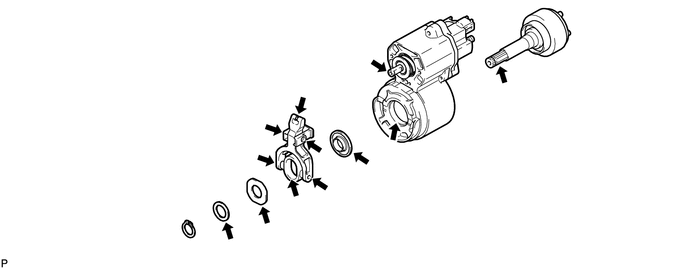
Text in Illustration 
High-temperature Grease - - -
Install the starter clutch sub-assembly into the magnet starter switch assembly.
Note
Make sure that the bearing does not disengage from the starter clutch sub-assembly.
-
Install the 3 starter washers and pinion drive lever with the snap ring.
-
-
INSTALL STARTER DRIVE HOUSING ASSEMBLY
-
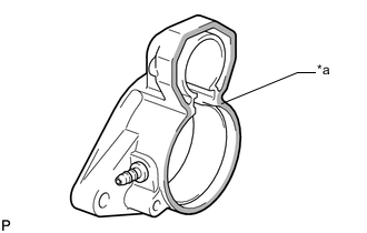
Text in Illustration *a Seal Packing Apply a light coat of seal packing to the surface of the starter drive housing assembly that contacts the starter magnet switch assembly.
Seal packing Toyota Genuine Seal Packing 1121C, Three Bond 1121C or equivalent -
Install the starter drive housing assembly to the magnet starter switch assembly with the 2 bolts.
- Torque:
- 6.0 N*m { 61 kgf*cm, 53 in.*lbf }
-
-
INSTALL STARTER INTERNAL GEAR
-
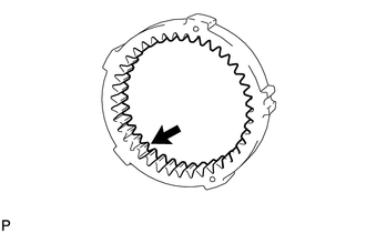
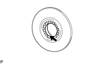
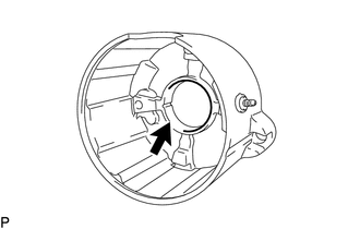
Apply high-temperature grease to the portion indicated by the arrow in the illustration.
Text in Illustration High-temperature Grease -
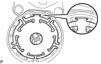
Install the starter internal gear to the magnet starter switch assembly.
Note
Make sure the internal gear protrusion indicated by the arrow in the illustration is aligned with the groove on the bottom side of the magnet starter switch assembly.
-
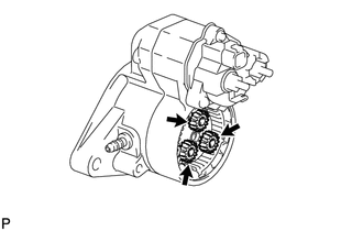
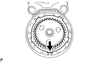
Apply high-temperature grease to the 3 starter planetary gears.
Text in Illustration High-temperature Grease -
Install the 3 starter planetary gears to the starter clutch sub-assembly.
-
-
INSTALL STARTER ARMATURE ASSEMBLY
-
Install the starter washer to the magnet starter switch assembly.
Note
Make sure that the starter washer is securely seated in the groove.
-
Apply high-temperature grease to the portion indicated by the arrow in the illustration.
Text in Illustration High-temperature Grease -
Install the starter plate to the magnet starter switch assembly.
-
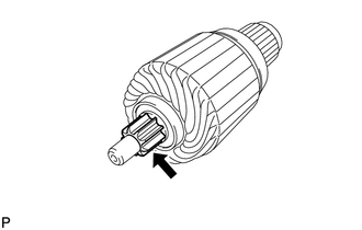
Apply high-temperature grease to the portion indicated by the arrow in the illustration.
Text in Illustration High-temperature Grease -
Install the starter armature assembly to the starter plate.
-
-
INSTALL STARTER YOKE ASSEMBLY
-
Install 2 new O-rings to the starter yoke assembly.
-
Install the starter yoke assembly to the magnet starter switch assembly.
-
-
INSTALL STARTER BRUSH HOLDER ASSEMBLY
-
Place the starter brush holder assembly on the starter armature assembly.
-
Using a screwdriver, hold the starter brush spring back and connect the 4 starter brushes to the starter brush holder assembly.
Note
Check that the positive (+) lead wires are not grounded.
-
Install the starter brush holder into the starter armature assembly.
-
Apply high-temperature grease to the portion indicated by the arrow in the illustration.
Text in Illustration High-temperature Grease -
Install the commutator end frame with the 2 screws.
- Torque:
- 3.9 N*m { 40 kgf*cm, 35 in.*lbf }
-
Install the 2 through bolts.
- Torque:
- 17 N*m { 173 kgf*cm, 12 ft.*lbf }
-
Install the nut to terminal C.
- Torque:
- 21 N*m { 214 kgf*cm, 15 ft.*lbf }
-
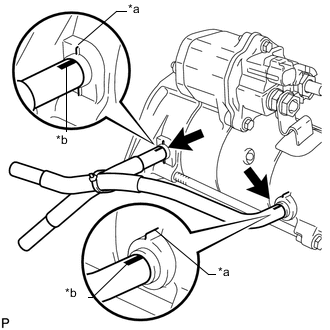
Text in Illustration *a Mark *b White Mark Install the 2 starter hoses to the starter assembly.
-
-
INSTALL STARTER CLUTCH PINION
-
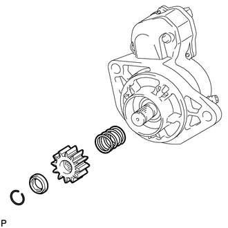
Install the starter drive spring, starter clutch pinion and pinion stop collar with the snap ring.
-