STARTER INSPECTION
PROCEDURE
-
INSPECT STARTER ASSEMBLY
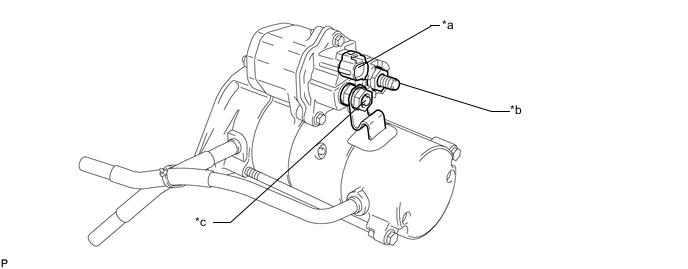
Text in Illustration *a Terminal 50 *b Terminal 30 *c Terminal C - - CAUTION:
As a large electric current passes through the cable during this inspection, a thick cable must be used. If not, the cable may become hot and cause injury.
Note
The following tests must be done within 3 to 5 seconds to prevent the coil from burning out.
-
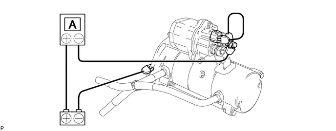
Perform the operation test without load.
-
Grip the starter assembly in a vise.
-
Connect the battery and an ammeter to the starter assembly with terminal 30 disconnected.
Note
Do not connect terminal 30 to the battery in this step.
-
Connect terminal 30 to the battery and check that the starter rotates smoothly and steadily while the pinion gear is moving outward. Then measure the current.
Standard current 200 A or less at 11 V If the result is not as specified, repair or replace the starter assembly.
-
-
-
INSPECT STARTER ARMATURE ASSEMBLY
-
Inspect the commutator for an open circuit.
-
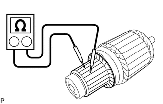
Measure the resistance according to the value(s) in the table below.
Standard Resistance Tester Connection Condition Specified Condition Commutator Always Below 1 Ω If the result is not as specified, replace the armature assembly.
-
-
Inspect the commutator for a short circuit.
-
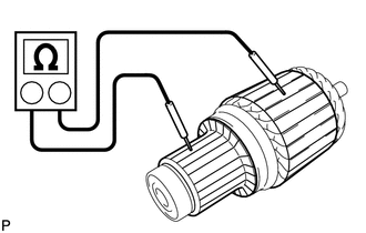
Measure the resistance according to the value(s) in the table below.
Standard Resistance Tester Connection Condition Specified Condition Commutator - Armature coil core Always 10 kΩ or higher If the result is not as specified, replace the armature assembly.
-
-
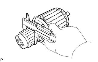
Using a vernier caliper, measure the commutator diameter.
Standard diameter 36.0 mm (1.42 in.) Minimum diameter 35.0 mm (1.38 in.) If the diameter is less than the minimum, replace the armature assembly.
-
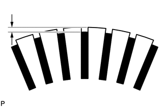
Measure the undercut depth of the commutator.
Standard undercut depth 0.7 mm (0.0276 in.) Minimum undercut depth 0.2 mm (0.00787 in.) If the undercut depth is less than the minimum, increase the depth using a hacksaw blade.
-
Check that the bearing rotates smoothly.
If necessary, replace the starter armature assembly.
-
Inspect the commutator circle runout.
-
Place the commutator on V-blocks.
-
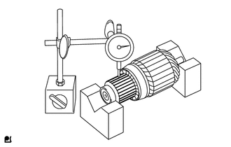
Using a dial indicator, measure the circle runout.
Maximum circle runout 0.05 mm (0.00197 in.) If the runout is more than the maximum, correct it with sandpaper (#400) or replace the armature assembly.
-
-
-
INSPECT STARTER YOKE ASSEMBLY
-
Inspect the field coil for an open circuit.
-
Measure the resistance according to the value(s) in the table below.
Standard Resistance Tester Connection Condition Specified Condition Terminal C plate - Brushes Always Below 1 Ω If the result is not as specified, replace the starter yoke assembly.
-
-
Inspect if the field coil is grounded.
-
Measure the resistance according to the value(s) in the table below.
Standard Resistance Tester Connection Condition Specified Condition Brushes - Starter yoke body Always 10 kΩ or higher If the result is not as specified, replace the starter yoke assembly.
-
-
-
INSPECT STARTER BRUSH
-
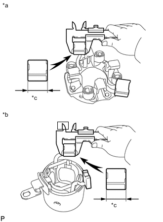
Text in Illustration *a Brush Holder Side: *b Starter Yoke Side *c Length Using a vernier caliper, measure the brush length.
Standard length 21.0 mm (0.827 in.) Minimum length 12.0 mm (0.472 in.) If the length is less than the minimum, replace the brush holder and starter yoke assembly.
-
-
INSPECT STARTER BRUSH HOLDER ASSEMBLY
-
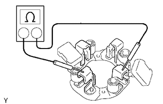
Measure the resistance according to the value(s) in the table below.
Standard Resistance Tester Connection Condition Specified Condition Positive (+) brush holder - Negative (-) brush holder Always 10 kΩ or higher If the result is not as specified, replace the brush holder assembly.
-
Inspect the load of the brush spring.
-
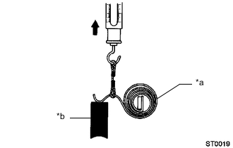
Text in Illustration *a Brush Spring *b Brush Take a pull scale reading immediately after the brush spring separates from the brush.
Standard spring installed load 36 N (3.6 kgf, 8.0 lbf) Minimum spring installed load 12 N (1.2 kgf, 2.7 lbf) If the spring installed load is less than the minimum, replace the brush holder assembly.
-
-
-
INSPECT STARTER CLUTCH SUB-ASSEMBLY
-
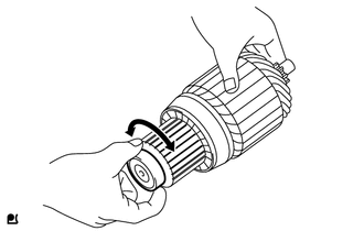
Check the starter clutch operation.
-
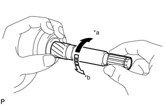
Text in Illustration *a Free *b Lock Hold the clutch and bearing with one hand and turn the shaft with the other. Check that the inner sleeve turns easily in the "free" direction but cannot turn in the "lock" direction as shown in the illustration.
If the starter clutch sub-assembly does not operate as specified, replace the starter clutch sub-assembly.
-
-
-
INSPECT MAGNET STARTER SWITCH ASSEMBLY
-
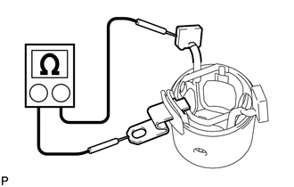
Check the pull-in coil for an open circuit.
-
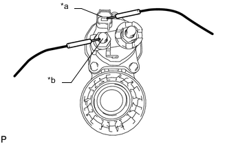
Text in Illustration *a Terminal 50 *b Terminal C Measure the resistance according to the value(s) in the table below.
Standard Resistance Tester Connection Condition Specified Condition Terminal 50 - Terminal C Always Below 1 Ω If the result is not as specified, replace the magnet starter switch assembly.
-
-
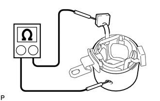
Check the hold-in coil for an open circuit.
-
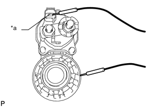
Text in Illustration *a Terminal 50 Measure the resistance according to the value(s) in the table below.
Standard Resistance Tester Connection Condition Specified Condition Terminal 50 - Housing Body Always Below 2 Ω If the result is not as specified, replace the magnet starter switch assembly.
-
-